Traditionally, AJA’s NTV2 SDI devices processed active video and ancillary data using separate data paths in the hardware. This is still very much the case, although the introduction of Anc inserter/extractor firmware has created further options.
CONTENTS:
Common Ancillary Data Types
The common Ancillary Data Types are audio, timecode, VPID, and Closed Captions.
Embedded Audio
Embedded audio in HANC is normally handled by the Audio System(s) in firmware — see Audio System Operation for more information.
Devices that have Anc Extractor firmware are able to capture the “raw” audio packets from HANC … then decode them per SMPTE/AES specifications. See SDI Anc Packet Capture (below) for information on how to do this.
Timecode
The timecode aspects of NTV2’s SDK and firmware has its origins in the early 2000s — when NTV2 devices were SD-only, and the SMPTE 12M spec was still evolving. FPGA space was very tight in those days, including the number of registers available … which is one reason why the same registers were used for RP-188 capture and playout.
- Two 32-bit registers are required to store a timecode value:
- one for the low-order 32 bits;
- another for the high-order 32 bits
- An extra register is used to hold the extra “Distributed Binary Bits” (DBB) information per SMPTE 12M and RP-188.
- In the SDK, these three register values are represented by the NTV2_RP188 data type, and the older RP188_STRUCT data type.
On older devices (i.e. those that don’t support “stacked audio” — see NTV2DeviceCanDoStackedAudio) and those without bidirectional SDI connectors (see NTV2DeviceHasBiDirectionalSDI), one general-purpose register triplet is used to store an SDI input’s timecode and also provide a place to specify a timecode for SDI output. In other words, one register triplet is used for reading a timecode from, say, SDI In 1 and for writing a timecode to, say, SDI Out 1. The Hi/Lo-order general-purpose timecode registers are “write-only” for SDI output; and “read-only” for SDI input. In other words, reading those registers yields the received input timecode, while writing those registers sets the output (playout) timecode.
- Note
- This inability to read back what’s been written into the register is very different behavior from nearly all other NTV2 registers. For devices that follow this old model, it’s impossible to fetch the output timecode value that was written for playout. So beware that when CNTV2Card::SetRP188Data is called on these older devices, it’s not possible to find out what was “set”, since CNTV2Card::GetRP188Data is always reading the SDI input’s timecode.
On newer devices that have bi-directional SDI connectors (i.e. both NTV2DeviceCanDoStackedAudio and NTV2DeviceHasBiDirectionalSDI return true), CNTV2Card::GetRP188Data will return the corresponding SDI output’s timecode if the SDI spigot is configured for output (see CNTV2Card::SetSDITransmitEnable).
For End-to-End (E-E) mode, i.e. when an SDI input is connected directly to an SDI output, to pass through timecode obtained from an SDI input…
Embedded SDI Timecode Input
Any RP-188 data in the SDI input video with DBB-1 data matching the input’s current RP-188 source select filter (see CNTV2Card::SetRP188SourceFilter) will be placed into the input’s RP-188 registers.
There are two ways to receive input timecode:
- Note
- Regarding High Frame Rates (>30fps): When reading timecode for any input faster than 30fps, you’ll see a duplicate frame count in two successive frames — but in the latter frame, the field bit will be set, and the DBB will indicate a value of 0x02 (VITC2). This is the SMPTE ST-12M-preferred way of sending >30fps timecode. The 12M specification says there are systems that won’t conform to this transmission convention, so receivers that want to support them will need to be flexible.
- Example: Capturing Embedded SDI Timecode Without AutoCirculate
SetUpRP188
{
{
if (!userDefinedDBB == 0)
{
inputFilter = 0x02;
else if (!isKonaLHi)
inputFilter = 0x01;
}
}
{
if (!userDefinedDBB)
}
}
GetReceivedTCForChannel
{
outReceivedLTC.
Set(); outReceivedVITC1.Set(); outReceivedVITC2.Set();
inCard.
ReadRegister (gChToRP188DBBRegNum[inChannel], receivedAnyRP188,
BIT(16), 16);
if (!receivedAnyRP188)
return false;
switch (inputFilter)
{
case 0x0000:
inCard.
ReadRegister(gChToRP188DBBRegNum[inChannel], &receivedLTC,
BIT(17), 17);
if (receivedLTC)
break;
case 0x0001:
inCard.
ReadRegister (gChToRP188DBBRegNum[inChannel], receivedLTC,
BIT(18), 18);
if (receivedLTC)
{
outReceivedLTC.DBB |=
BIT(18);
}
inCard.
ReadRegister (gChToRP188DBBRegNum[inChannel], receivedVITC1,
BIT(17), 17);
if (receivedVITC1)
{
outReceivedVITC1.
DBB = inCard.
ReadRegister (gChToRP188DBBRegNum[inChannel]);
outReceivedVITC1.
Low = inCard.
ReadRegister (gChannelToRP188Bits031RegisterNum[inChannel]);
outReceivedVITC1.
High = inCard.
ReadRegister (gChannelToRP188Bits3263RegisterNum[inChannel]);
}
break;
default:
inCard.
ReadRegister (gChToRP188DBBRegNum[inChannel], receivedLTC,
BIT(18), 18);
if (receivedLTC)
{
outReceivedLTC.DBB |=
BIT(18);
}
inCard.
ReadRegister (gChToRP188DBBRegNum[inChannel], receivedVITC1,
BIT(19), 19);
inCard.
ReadRegister (gChToRP188DBBRegNum[inChannel], receivedVITC2,
BIT(17), 17);
if (receivedVITC1 && receivedVITC2)
{
}
else
{
if (receivedVITC1)
if (receivedVITC2)
{
else
}
}
}
return true;
}
Embedded SDI Timecode Output
When RP-188 output is enabled for an SDI output (by calling CNTV2Card::SetRP188Mode and passing it NTV2_RP188_OUTPUT), whatever RP-188 data was written into the RP-188 registers is inserted into the HANC of the SDI output video after the next output VBI on the appropriate line (even when “tall” or “taller” VANC Frame Geometries are in use):
- SD NTSC 720×486 — lines 10 & 273
- SD PAL 720×576 — lines 7 & 320
- HD 1280×720 & 1920×1080 & up — line 10
There are two ways to transmit timecode:
- When using AutoCirculate Playout, generally, AutoCirculate automatically configures the RP-188 registers, and writes the appropriate registers at the proper time using the provided timecode value(s).
- When not using AutoCirculate, for a given SDI output connector, do the following:
- During setup…
- For each outgoing frame, call CNTV2Card::SetRP188Data to specify the RP-188 timecode to embed in the next outgoing frame (for a given SDI output connector).
- Note
- Starting in SDK 15.0, when doing AutoCirculate Playout with both AUTOCIRCULATE_WITH_RP188 and AUTOCIRCULATE_WITH_ANC on an IP device (see NTV2DeviceCanDoIP) that supports SMPTE 2110 (see NTV2DeviceCanDo2110), CNTV2Card::AutoCirculateTransfer will automatically add all channel-relevant timecodes found in the AUTOCIRCULATE_TRANSFER::acOutputTimeCodes buffer into the relevant RTP packets in the AUTOCIRCULATE_TRANSFER::acANCBuffer and/or AUTOCIRCULATE_TRANSFER::acANCField2Buffer (see RTP Anc Buffer Data Format), augmenting what was already placed there. If this is not desired, and you’d prefer to use your own timecode packets, then call CNTV2Card::AutoCirculateInitForOutput without specifying AUTOCIRCULATE_WITH_RP188, then add the timecode AJAAncillaryData packet(s) to the AJAAncillaryList before calling AJAAncillaryList::GetIPTransmitData (prior to calling AUTOCIRCULATE_TRANSFER::SetAncBuffers and CNTV2Card::AutoCirculateTransfer).
Analog LTC Input
On AJA devices having one or more analog LTC inputs — or devices that can receive LTC from the Reference Input — there’s a pair of registers for each LTC input that store the received timecode: one for the high-order 32 bits, the other for the low-order 32 bits. Historically, the LTC input circuitry has relied on the prevailing input’s frame rate to know when to fetch and decode the incoming analog timecode signal and latch the detected timecode values.
- Note
- On newer multi-format-capable devices (see NTV2DeviceCanDoMultiFormat), the incoming LTC frame rate must match a designated SDI input’s frame rate (see CNTV2Card::SetAnalogLTCInClockChannel).
There are two ways to input analog LTC:
- Using AutoCirculate Capture :
- Without AutoCirculate :
bool canReadAnalogLTC (false);
bool isMultiFormatMode (false);
canReadAnalogLTC = true;
if (isMultiFormatMode)
while (::WaitForInputFieldID(
NTV2_FIELD0, whichSDIInputHasInputClock))
{
bool analogLTCPresent (false);
if (canReadAnalogLTC)
if (analogLTCPresent)
{
std::cout << analogLTC << std::endl;
}
}
Analog LTC Output
On AJA devices having one or more analog LTC outputs — there’s a pair of registers for each LTC output for placing the timecode to be transmitted: one for the high-order 32 bits, the other for the low-order 32 bits.
LTC output can be driven “end-to-end” by its corresponding LTC input.
- Note
- On newer multi-format-capable devices (see NTV2DeviceCanDoMultiFormat), the outgoing LTC frame rate must match a designated SDI output’s frame rate (see CNTV2Card::SetAnalogLTCOutClockChannel).
There are two ways to output analog LTC:
Timecode Display
In SDK 17.5, AJA committed to resolving the High Frame-Rate (HFR) timecode display problem. SMPTE ST 12-1 (formerly SMPTE 12M) timecode only allows enough bits to code for up to 30 frames per second (with the standard officially supporting 24, 25, 30 drop-frame, and 30 non-drop). SMPTE ST 12-3 provides a way to encode rates above 30 fps by reusing DBB, field and color frame bits. However, neither standard addresses how timecode is actually presented to a human being, particularly for high frame rates, which has led to multiple de facto “standards” from multiple vendors. What follows below is a description of what is henceforth the AJA standard, which is based on HFR presentation in various video tape machines (the binary representation of this is what eventually became SMPTE ST 12-3) as well as software like the Autodesk Suite that requires users to know (and enter) exact frame values.
The AJATimeCode class supports 2 types of display conventions. Each is independent of the other, and may be matched as needed.
- Frame-Count convention
- Delimiter convention
Frame-Count convention applies only to the frame field of a timecode. There are 2 types:
- LFR (Standard or Default)
- Frame values in the frame field are restricted by convention to be less than 30. This supports timecode used in legacy video standards and common in legacy VTRs and hardware.
- Frame number is unaltered when frame rate is less than or equal to 30 fps.
- Frame number is divided by 2 when frame rate is greater than 30 fps. Fractional frame values are truncated.
- Frame number is divided by 4 when frame rate is greater than 60 fps. Fractional frame values are truncated.
- Example: Given a 60 fps non-drop frame rate, the frame roll for frames 0, 1, 2, 3, 4, ... 59, 60 are:
- AJA_TIMECODE_LEGACY (LFR):
00:00:00:00
00:00:00:00
00:00:00:01
00:00:00:01
00:00:00:02
…
00:00:00:29
00:00:01:00
- AJA_TIMECODE_STANDARD (LFR):
00:00:00:00
00:00:00.00
00:00:00:01
00:00:00.01
00:00:00:02
…
00:00:00.29
00:00:01:00
- HFR
- This uses the unaltered frame number in the frame field for both low and high frame rates.
- Example: Given a 60 fps non-drop frame rate, the frame roll for frames 0, 1, 2, 3, 4, … 59, 60 are:
- AJA_TIMECODE_LEGACY (HFR):
00:00:00:00
00:00:00:01
00:00:00:02
00:00:00:03
00:00:00:04
…
00:00:00:59
00:00:01:00
- AJA_TIMECODE_STANDARD (HFR):
00:00:00#00
00:00:00#01
00:00:00#02
00:00:00#03
00:00:00#04
…
00:00:00#59
00:00:01#00
Delimiter convention applies to the delimiter character-sets which separate fields in the timecode presentation. There are 2 types:
- AJA_TIMECODE_LEGACY
- This is the default timecode Delimiter convention and is widely used in legacy applications. It is not preferred because its presentation is ambiguous when converting between frame values and timecode for high frame rate video.
- Non-Drop-frame video uses a colon (
":") as a delimiter between all fields (hours/minutes/seconds/frames).
Example: "01:02:03:04"
- Drop-frame video also uses a colon (
":") as a delimiter between fields hours/minutes/seconds, except between fields seconds/frames, which uses a semi-colon (";").
Example: "01:02:03;04"
- This Delimiter convention is the same for both LFR and HFR Frame-Count conventions, which can lead to misinterpretation.
- AJA_TIMECODE_STANDARD
- AJA Standard presentation convention is updated and recommended for current and ongoing adoption.
- Timecode presentation is unambiguous when converting between frame values and timecode strings for high frame rate video.
- Does not break existing low frame rate (LFR) timecode use cases.
- LFR and HFR Frame-Count presentations are distinct and unambiguous.
- In both LFR and HFR presentations, the delimiter between hours/minute/second delimiters are the same:
- Colon (
":") for non-drop-frame timecode;
- Semicolon (
";") for drop-frame timecode.
- LFR Frame-Count
- seconds/frame delimiter:
- identical to the other delimiters if the field flag is 0 (or unknown).
- a period (
".") if the field flag is 1
- Roll Sequence Examples:
- Drop Frame:
01;02;03;00
01;02;03.00
01;02;03;01
- Non-Drop Frame:
01:02:03:00
01:02:03.00
01:02:03:01
- HFR Frame-Count
- seconds/frame delimiter is always a pound sign (
"#")
- Roll Sequence Examples:
- Drop Frame:
01;02;03#58
01;02;03#59
01;02;04#00
- Non-Drop Frame:
01:02:03#58
01:02:03#59
01:02:04#00
- For frame rates greater than 60, three padded zeros (
"000") is used for the frame count instead of two ("00").
- Roll Sequence Examples for 120 fps drop frame:
01;02;03#099
01;02;03#100
01;02;04#101
- Note
- • Code that looks for a colon (
":") or semicolon (";") in the seconds/frame delimiter position to detect drop/non-drop will need to change, since it doesn’t work with AJA_TIMECODE_STANDARD. AJA recommends using the AJATimeCode::QueryIsDropFrame method, since it supports all Delimiter conventions presented here.
-
• For HFR, follow SMPTE ST 12-3 interpretation of the binary data; otherwise follow SMPTE ST 12-1 for LFR.
VPID
VPID is the acronym used for Video Payload IDentification, a four-byte ancillary data packet transmitted in the HANC region of the SDI video signal, per SMPTE standard ST352. Its packet DID is 0x41 and SDID is 0x01.
Input / Record
On AJA devices with one or more SDI inputs (3G or faster), when a signal is present, the firmware automatically looks for and detects VPID (Video Payload IDentifier) packets on link A (and link B, if present), and stores the extracted VPID data value(s) into separate register(s), one per link.
There are two methods to read input VPID:
- All devices:
- Devices that have Anc Extractor firmware described in SDI Anc Packet Capture (below) can capture the “raw” HANC VPID packet data … then decode it per SMPTE specifications.
Once the 4-byte VPID value has been read, it can be decoded, per SMPTE specifications. The CNTV2VPID class can be used as a convenience to query all the various metadata that describes the input signal.
Output / Playback
On AJA devices with one or more SDI outputs (3G or faster), there are two VPID output payload registers for each SDI output (one for Link A, another for Link B). When the driver is running in NTV2TaskMode NTV2_STANDARD_TASKS (retail) or NTV2_OEM_TASKS, it will automatically write the proper VPID payload value(s) into these registers when the output video standard is set. The SDI output’s Anc embedder, upon seeing a valid VPID payload in the respective payload register, will automatically insert a VPID packet in the outgoing SDI data stream.
Closed-Captions
Closed-captions are an important category of ancillary data. The popular captioning standards (by transport):
- Analog (SD) “Line 21”:
- US NTSC 525i: EIA-608
- PAL 625i: Teletext OP-42
- SDI: Encoded into one or more ancillary data packets, per SMPTE ST-291. There are several captioning standards that encapsulate their data into SMPTE 291 packets:
- U.S. NTSC CEA-608
- U.S. NTSC CEA-708
- Teletext OP-47
- ARIB STD-B37
- etc.
- TCP/IP:
- SMPTE ST 2022: Same as SDI (above) with SDI data frame encapsulated into network packet(s).
- SMPTE ST 2110: Same as SDI (above) with SMPTE ST-291 packets encoded into separate RTP stream (separate from video and audio RTP streams).
- HDMI: Only supports Open Captions (burned-in); Closed Captions not supported.
SDI Anc Packet Capture
There are two ways to capture any/all Ancillary data packets:
- Use Anc Extractor firmware: (Preferred)
- Available on most devices — check NTV2DeviceCanDoCustomAnc.
- Ancillary data is automatically extracted and placed into a separate area of the device frame buffer.
- With AutoCirculate :
- Without AutoCirculate :
- Each Anc Extractor is capable of filtering certain types of ancillary data packets:
- The default maximum per-field ancillary data buffer capacity is 8K by default, or 16K per-frame, including overhead. Please submit a Ticket if you need to change this.
- Use VANC frame geometry (for older AJA devices)
- 4K/UHD or larger rasters (i.e. NTV2FrameGeometry ≥ NTV2_FG_4x1920x1080) aren’t supported, and likely never will be.
- Only NTV2_FBF_10BIT_YCBCR and NTV2_FBF_8BIT_YCBCR buffer formats are officially supported. Others may work, but are untested.
- Signal paths involving CSCs/LUTs between the SDI input and the Frame Store may corrupt the VANC data.
- HANC is (obviously) not available in the frame buffer.
- Call CNTV2Card::SetVANCMode to enable the “tall” or “taller” frame geometry.
- See VANC Frame Geometries (below) for details on the locations of the SMPTE VANC lines in the frame buffer.
- After the frame has been transferred to the host, to obtain the ancillary data:
TIP: The “NTV2Watcher” tool’s Ancillary Data Inspector is useful for diagnosing issues with ancillary data capture.
Ancillary Packet Filtering
For devices that support custom Anc capture, each SDI input has an “Anc Extractor” widget associated with it. Each of these widgets have a filter that can exclude unwanted packets based on a packet’s Data IDentifier (DID). Each filter is configured using five 32-bit registers, each register accommodating four DID byte values, resulting in the ability to filter (exclude) up to 20 different types of packets.
- A non-zero byte value in a filter register will cause the Extractor to skip packets whose DID matches that byte value.
- A zero byte value is always ignored by the Extractor.
- It is not an error to have the same DID in multiple byte positions in the filter registers.
By default, the SDI input’s Anc extractor widget is configured when CNTV2Card::AutoCirculateInitForInput (or CNTV2Card::AncExtractInit) are called, and will automatically exclude a default set of packet types. For example, VPID, VITC/ATC, audio control and audio packets are filtered by default, because existing device firmware automatically handles audio, timecode and VPID, making such data available by way of other high-level API calls.
But what if, for example, you need to parse the raw data that’s inside SMPTE 299M audio packets?
Disabling All Filtering
To disable all filtering of incoming ancillary data packets, pass an empty NTV2DIDSet to CNTV2Card::AncExtractSetFilterDIDs.
For SDKs prior to version 13.0, pass zero to CNTV2Card::WriteRegister for each filter register for the Anc extractor associated with the SDI input of interest:
- SDI In 1: registers 4108-4112 (inclusive)
- SDI In 2: registers 4172-4176 (inclusive)
- SDI In 3: registers 4236-4240 (inclusive)
- SDI In 4: registers 4300-4304 (inclusive)
- SDI In 5: registers 4364-4368 (inclusive)
- SDI In 6: registers 4428-4432 (inclusive)
- SDI In 7: registers 4492-4496 (inclusive)
- SDI In 8: registers 4556-4560 (inclusive)
- Note
- Changing packet filtering takes effect at the next captured frame.
- Warning
- Disabling packet filtering can result in an extraordinary amount of captured ancillary data.
Filtering Specific Packet Types
To exclude packets having specific DIDs, build an NTV2DIDSet that contains the packet DIDs you wish to exclude, then pass the set to CNTV2Card::AncExtractSetFilterDIDs. For SDKs prior to version 13.0, pack up to four DIDs to be excluded into a 4-byte longword, and write the longword (using CNTV2Card::WriteRegister) into one of the filter registers associated with the SDI input of interest (see above list).
Restoring Default Filtering
You can also reset the ANC filtering to the default filter set:
For SDKs prior to version 13.0, you must copy the default filter register values at startup (using CNTV2Card::ReadRegister) to local variables, then restore them afterward (using CNTV2Card::WriteRegister) later. Use the registers that are associated with the SDI input of interest.
It’s a good practice to save the existing filter settings, change them to what’s needed for whatever processing is necessary, and then restore them afterward:
. . .
{
dids.insert(0xA0);
dids.insert(0xA1);
dids.insert(0xA4);
dids.insert(0xA5);
}
Ancillary Data Space Limitations
Rarely does the ancillary data transmitted with a field of video exceed 5KB (or 10KB for a frame of interlaced video) … but it’s possible. If your application must accommodate more than 72KB of ancillary data, you’ll need to enlarge the driver’s ancillary data region.
The NTV2 driver uses two virtual registers (kVRegAncField1Offset and kVRegAncField2Offset) to control where the Anc Extractors start writing extracted packet data into (current) frame memory. When the driver starts up, it’s configured to use 0x12000 bytes (~72k) of space per field at the very bottom of each 8MB/16MB/… frame on the device (depending on video format and pixel format).
If you know the largest byte count you’ll encounter for each field, add some padding, then call CNTV2Card::AncSetFrameBufferSize with those values. For SDKs prior to version 13.0, write the Field 2 maximum byte count to the kVRegAncField2Offset register, then set the kVRegAncField1Offset register to the sum of both byte counts.
- Warning
- Itʼs possible to reserve a very large ancillary data space that actually runs into the video in the frame buffer.
To programmatically check if the Anc space intersects video in the frame buffer:
. . .
ULWord byteOffset(0), byteCount(0);
if (fd.GetTotalBytes() > byteOffset)
FAIL("Anc in video!");
Maximizing Ancillary Data Capture Capacity
- Determine the largest raster your application is expected to handle.
- Determine the most “expensive” (in terms of memory) NTV2PixelFormat your application will need to use.
- Determine the “intrinsic” device frame buffer size that will be used for the video format and frame buffer format (8MB/16MB/etc.).
- Calculate the maximum available space for ancillary data in the device frame buffer. This is the distance, in bytes, from just past the last line of the raster to the bottom of the device frame buffer.
- Call CNTV2Card::AncSetFrameBufferSize, passing half the byte distance to each of the two parameters.
For example, 1080i video with a 10-bit YCbCr frame buffer format (without a “tall” or “taller” VANC geometry) is easily handled by an 8MB device frame buffer. The 1920x1080 raster requires the top 5,529,600 bytes of the device frame buffer, which leaves 2,859,008 bytes of space for ancillary data. If a 16MB frame buffer is used (see CNTV2Card::SetFrameBufferSize), the maximum possible anc space jumps to 11,247,616 bytes — a LOT of space!
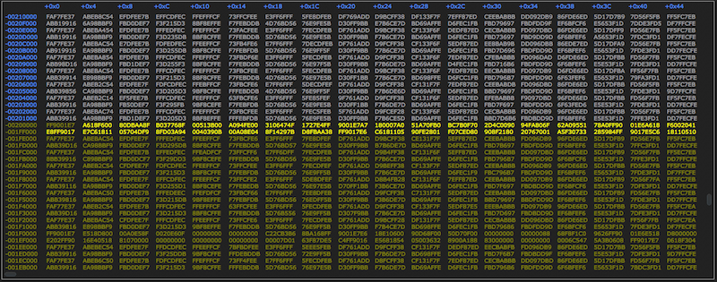
The Frame Buffer Inspector of “NTV2Watcher” readily illustrates how this works.
- Set it to the Raw view mode.
- Change the units used for the vertical ruler to Bytes From Top.
- Change the units used for the horizontal ruler to Bytes From Left Edge.
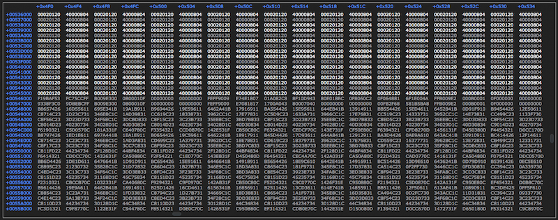
- Scroll down to the end of active video (EAV). This is where a noticeable boundary between illuminated and dimmed values indicate where changing pixel data ends. That offset – 0x00546000 – is the first safe (unchanging) byte of available ancillary buffer space.
- Scroll down further until the data is displayed in a yellow color. That is the ancillary data region.
SDI Anc Packet Playout
There are two ways to play out custom Ancillary data packets:
- Use Anc Inserter firmware: (Preferred)
- Available on most devices — check NTV2DeviceCanDoCustomAnc.
- Ancillary data packets are automatically inserted into the outgoing video stream when they’ve been properly formatted and placed into a separate area of the device frame buffer.
- Cannot output HANC (sorry).
- With AutoCirculate :
- Without AutoCirculate :
- On SDI devices and SMPTE 2022 firmware on IP devices, the parity bits for outgoing 10-bit UDWs are automatically recalculated by the Anc inserter, after reading the 8-bit UDWs out of the Anc Buffer, while embedding the packet data into the outgoing SDI data stream.
- Default per-field ancillary data buffer capacity is 8K by default, or 16K per-frame, including overhead. Please submit a Ticket if you need to change this.
- Use VANC frame geometry (for older AJA devices)
- 4K/UHD or larger rasters (i.e. NTV2FrameGeometry ≥ NTV2_FG_4x1920x1080) aren’t supported, and likely never will be.
- Only NTV2_FBF_10BIT_YCBCR or NTV2_FBF_8BIT_YCBCR buffer formats are officially supported. Others may work, but are untested.
- Signal paths involving CSCs/LUTs between the Frame Store and the SDI output may corrupt the VANC data.
- HANC obviously cannot be supported.
- Call CNTV2Card::SetVANCMode to enable the “tall” or “taller” frame geometry.
- See VANC Frame Geometries (below) for details on the locations of the SMPTE VANC lines in the frame buffer.
- Before transferring the frame to the device, set the contents of the VANC line(s)…
- If desired, use the Ancillary Data Classes — call AJAAncillaryList::GetVANCTransmitData.
- CAUTION: The device will transmit whatever Y/Cb/Cr values are in the VANC region of the buffer unfiltered, including illegal values, which can cause sync issues in downstream equipment. Be sure all values stored in the VANC lines are legal SMPTE.
- Note
- Because the outgoing line number can be specified when using the Anc Inserter, it's possible to overrun a line. Be certain that the data packets to be inserted on a given line will fit for the output video standard.
- Warning
- AJA strongly recommends NOT playing verbatim the same ancillary data packets captured by a firmware Anc Extractor through a firmware Anc Inserter. There are several reasons for this, and moreso if the output video format differs from the input format:
- Packets that are ordinarily embedded in output SDI automatically by the hardware (e.g. audio, ATC, VPID, EDH, etc.) should be filtered out. The AJAAncillaryList::StripNativeInserterGUMPPackets function can do this.
- HANC packets should be excluded (removed), since the Anc Inserters on most AJA devices are not designed to insert them, and aren’t expecting them.
- Some packet types may be irrelevant or not recommended for certain output video formats;
- e.g. packets that specifically are intended for Field 2 of interlaced video should be excluded from insertion into progressive video.
- Some packet types may require their payload data to change (e.g. if the output’s frame rate differs from the input’s).
- Some packets may need to be inserted on a different line.
TIP: The “NTV2Watcher” tool’s Ancillary Data Inspector is useful for diagnosing issues with ancillary data playout.
Anc Buffer Data Formats
This section details the format of the data in the ancillary data buffers.
SDI Anc Buffer Data Format
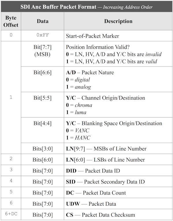
This is the default format in the host ancillary data buffers. The data bytes in the ancillary data buffer consist of one or more packets having the following format:
- Note
- While the first byte of each packet is set to
0xFF, this is not a protected value, and can legally occur within packet data. Software parsers must use the packet Data Count (DC) value to determine the length of each packet.
For Capture:
For Playout:
- Note
- During Playout, the packet checksums in the device ancillary data buffer are ignored. The Anc inserter/embedder firmware automatically recalculates each packet’s checksum as it enters the outgoing SDI stream.
RTP Anc Buffer Data Format
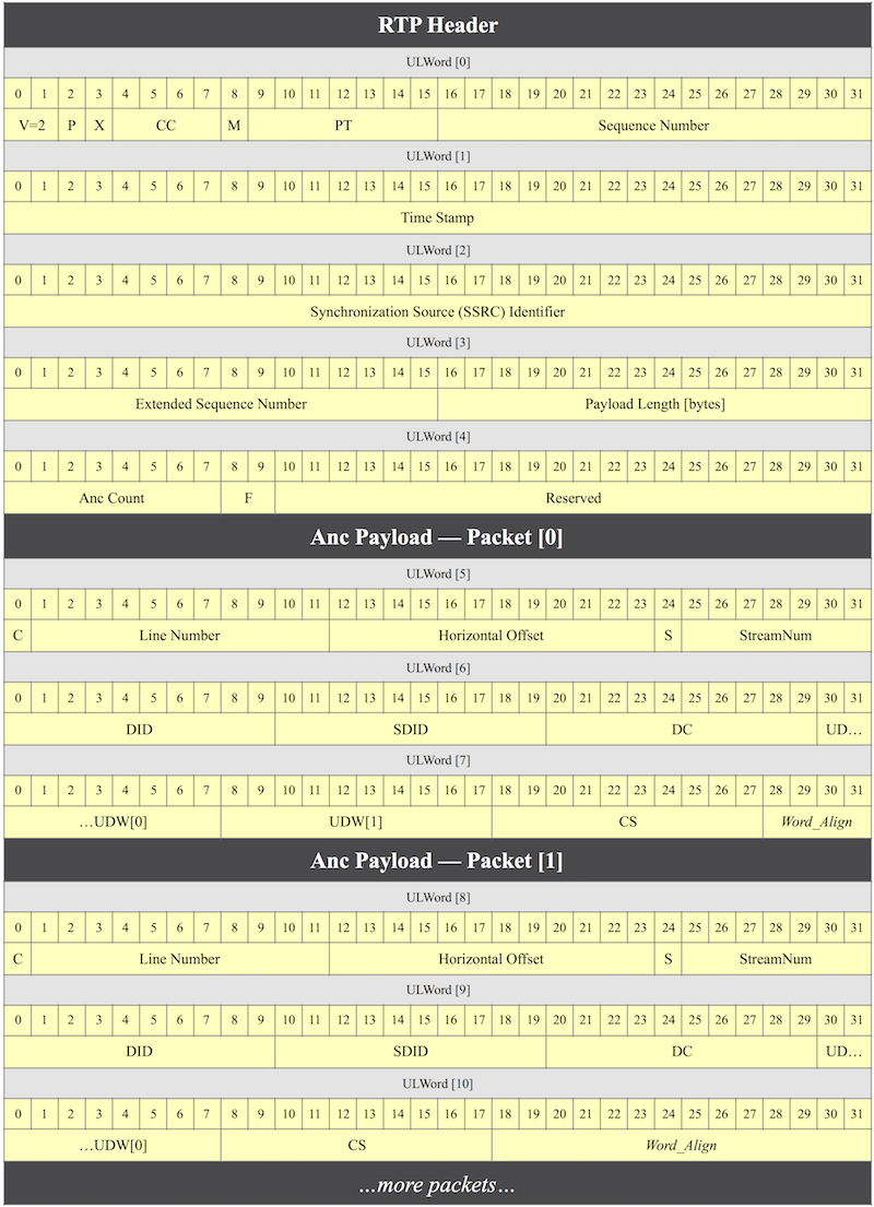
The data in the ancillary data buffer, except where noted (below), matches the RTP specification documented in SMPTE ST 291-1:
For Capture:
For Playout:
- Clients can write the data themselves per the RTP specification.
- Clients that generate the Anc data buffer contents themselves must set the Sequence Number field in the first longword of the RTP packet header to the total RTP packet bytecount, since AJA IP devices running 2110 firmware (KONA IP and Io IP) expect it there.
- AJAAncillaryList::GetTransmitData can be called to fill the host Anc data buffers from an AJAAncillaryList.
VANC Frame Geometries
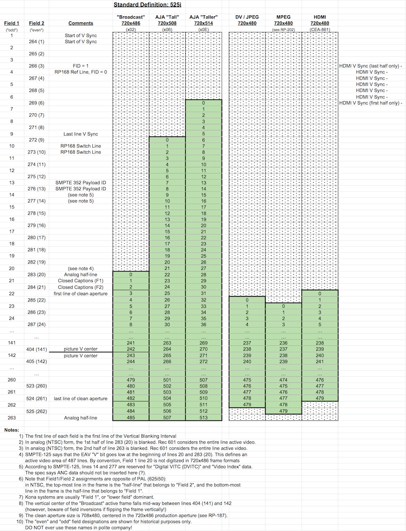
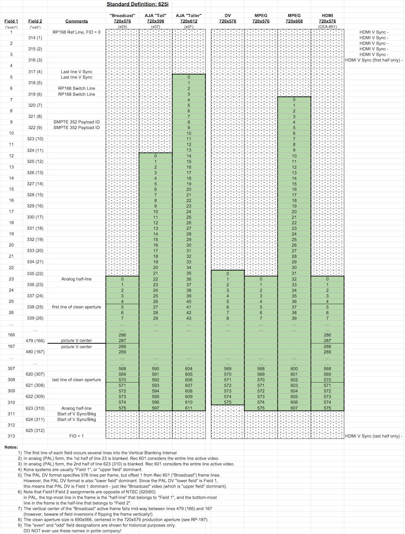
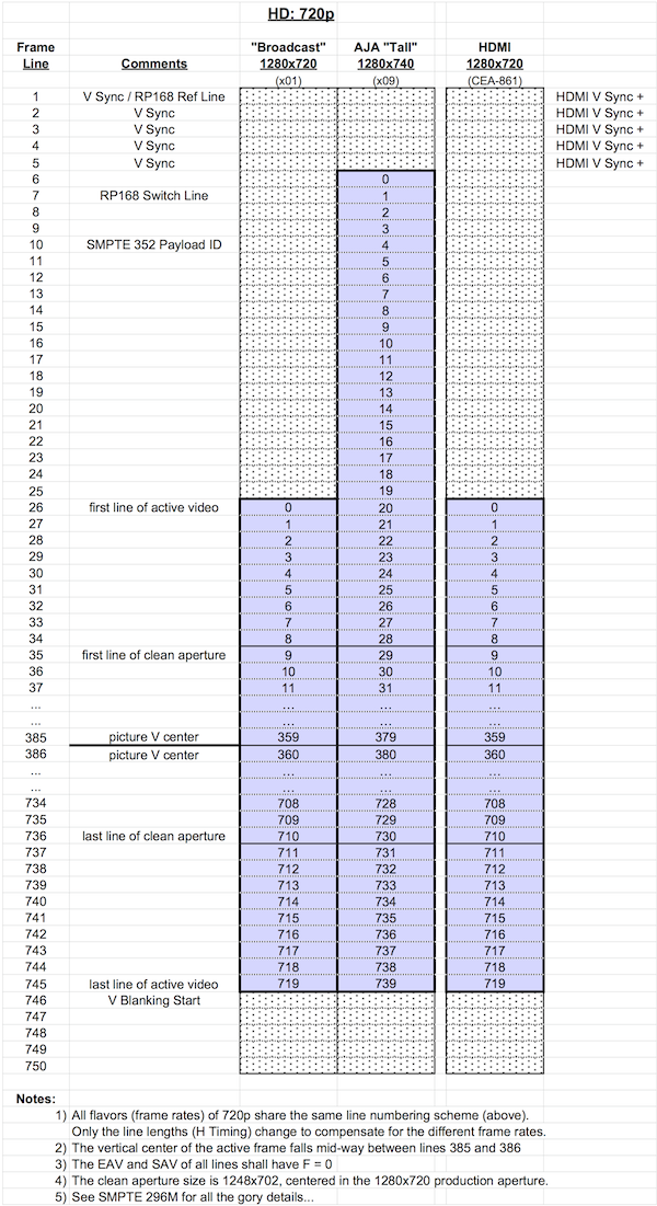
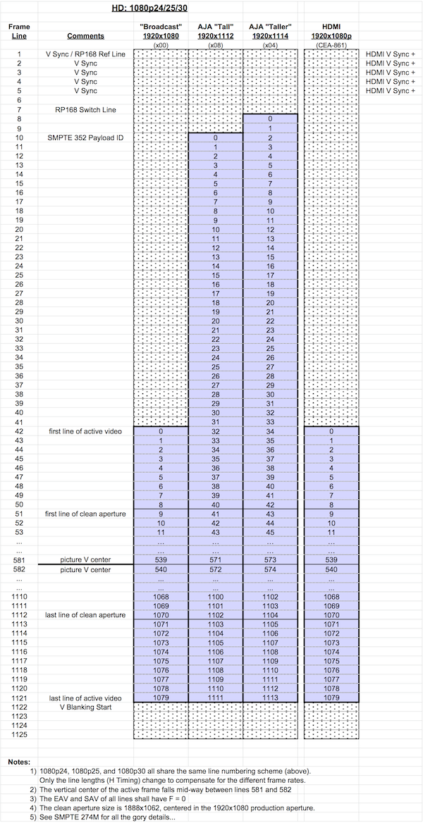
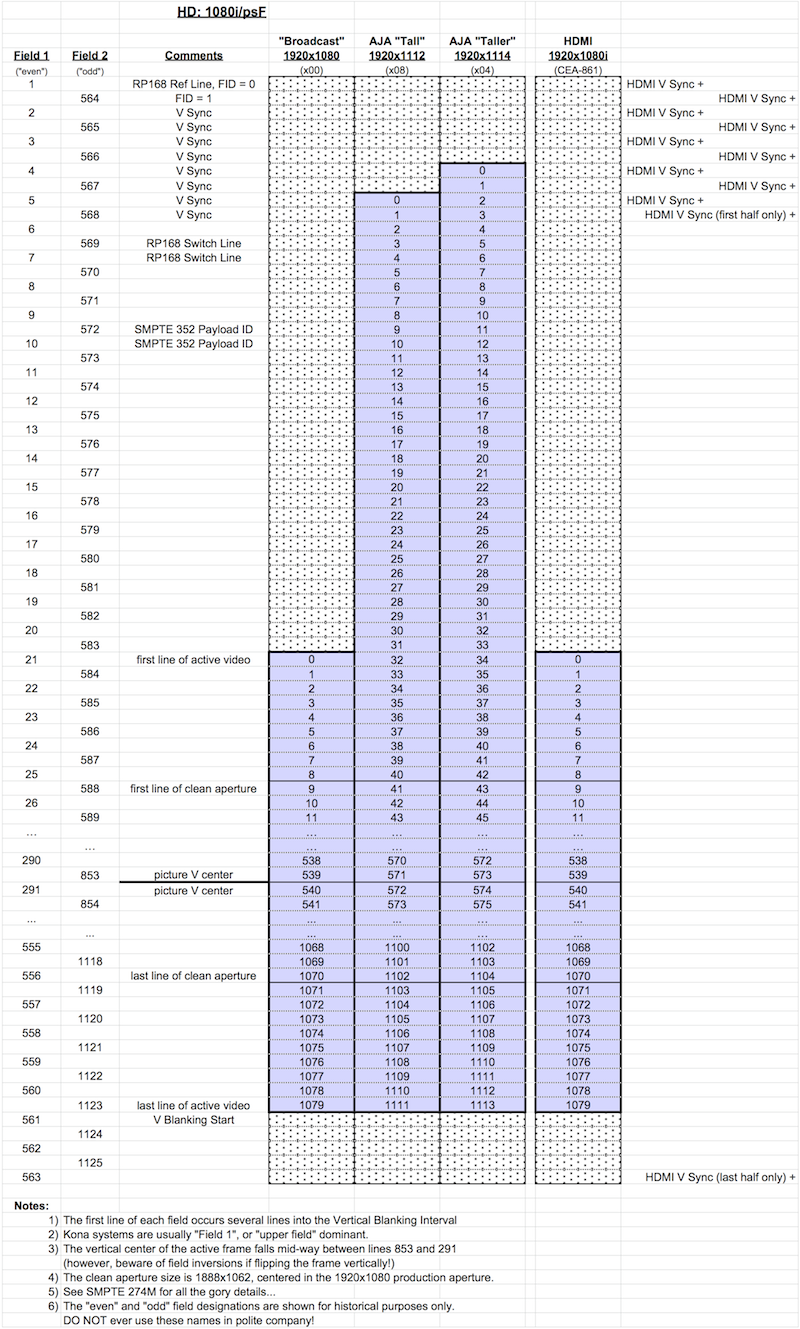
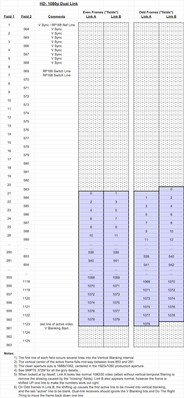
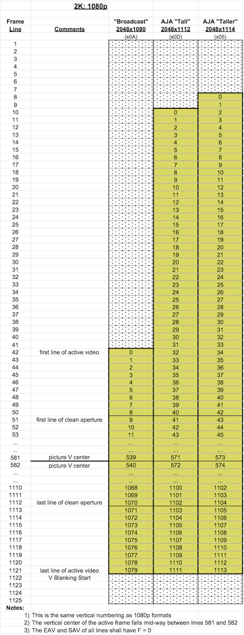
The older way of extracting or inserting ancillary data (VANC only) employs alternate frame geometries that have additional lines at the top of the video frame buffer. To enable VANC capture/playout, call CNTV2Card::SetEnableVANCData or CNTV2Card::SetVANCMode.
For historical reasons, there are both "tall" and "taller" geometries. The taller ones grab some extra lines that used to be omitted, but which turned out to contain useful information after all.
Note that using a VANC-enabled frame geometry will increase the size, in bytes, of the requisite host frame buffer versus the equivalent non-VANC geometry. Use CNTV2Card::GetFrameBufferSize function to determine how large the host frame buffer should be.
There are some considerations on which frame buffer formats should be used for capture or playout with VANC:
- NTV2_FBF_8BIT_YCBCR — This is the easiest format to use, but there’s a catch. Ordinarily, the least-significant 2 bits of 10-bit YCbCr pixel data are discarded when filling the 8-bit pixel data words in the frame buffer (in capture mode). This is fatal to ancillary data in the VANC lines, because per SMPTE ST-291, the most-significant 2 bits of the 10-bit data word can be dropped/ignored, not the least-significant 2 bits. Fortunately, the AJA device firmware can be told to store the LS 8 bits of each 10-bit word in the VANC area during capture (or left-shift by 2 bits during playout) by calling CNTV2Card::SetVANCShiftMode. Thus, when a frame is captured using NTV2_VANCDATA_8BITSHIFT_ENABLE mode, VANC lines can be easily parsed into Ancillary packets.
- Note
- NTV2_VANCDATA_8BITSHIFT_ENABLE mode is not implemented for SD 525i/625i video formats. This is due to historical reasons, since back when HD was introduced, SD typically carried ancillary data in other ways (e.g. line 21 for captions).
- NTV2_FBF_10BIT_YCBCR — With 10-bit YCbCr, ancillary data packets can be read/written from/to the VANC lines, but the scanning process is more difficult, due to the packing of 10-bit words in the frame buffer.
- Dual-link RGB video to/from YCbCr frame buffers generally won't work because the VANC data gets corrupted by the color-space converters. However, dual-link RGB video to/from RGB frame buffers (directly from/to the SDI spigots) will work.
- Note
- Mixer/Keyer widgets on newer devices (generally, those that support NTV2DeviceCanDoCustomAnc) will pass VANC. Call CNTV2Card::GetMixerVancOutputFromForeground to determine if the Mixer is configured to pass foreground or background VANC. Call CNTV2Card::SetMixerVancOutputFromForeground to change the setting.
To Capture custom ancillary data packets using VANC lines in the frame buffer:
To Playout custom ancillary data packets using VANC lines in the frame buffer:
The spreadsheets that follow show, in detail for each video format, which lines contain VANC, and which ones contain video data.
SD 525i
SD 625i
HD 720p
HD 1080p
HD 1080i/psF
HD 1080p Dual-Link
2K: 1080p


