On this page:
Introduction
In simplest terms, NTV2 devices are essentially…
- a big chunk of SDRAM memory for buffering video frames and audio samples, which is tied to…
- an FPGA that determines what gets written or read to/from that memory (and where), plus…
- one or more video and/or audio signal inputs and/or outputs, and…
- a high-speed PCIe interface to a host computer, for rapidly reading or writing 32-bit registers, and transferring bulk data via DMA to/from the host.
In addition, the FPGA firmware implements “widgets“ that can process video data in a particular way (e.g., color correction, muxing/demuxing, etc.).
Hardware Characteristics
- PCI Interface
All NTV2 devices utilize Peripheral Component Interconnect (PCI) or Peripheral Component Interconnect Express (PCIe) to communicate with the host computer system (or with other PCI/PCIe peers on the same host).
- PCI Vendor ID
All AJA NTV2 devices have the same PCI vendor ID.
- Data Transfer
Direct Memory Access (DMA) is the only supported method of moving data between host memory and the hardware. All NTV2 devices have at least one DMA engine. (Programmed Input/Output, a.k.a. PIO is no longer supported.)
- Device Frame Buffer
All NTV2 devices have a fixed amount of Synchronous Dynamic Random Access Memory (SDRAM). The FPGA is the SDRAM controller, which controls the output of video (and metadata, such as audio and anc) from RAM, the input of video (and metadata) into RAM, the PCI interface to/from RAM, and RAM refresh.
- Frame Buffer Layout
The FPGA is programmed with firmware that implements a number of video I/O and signal-processing “widgets”, plus other programming to handle other signal and data I/O.
The vast majority of the SDRAM frames are used for storing video raster data.
Audio ring buffer storage is located at the very top of SDRAM. As such, the uppermost frame(s) should be avoided for video. See Audio System Operation for more information.
Video data in the device frame buffer is always stored full-frame. Interlaced video is always stored in the frame buffer with the first line of Field 1 (F1L1) at the top of the buffer, followed by the first line of Field 2 (F2L1), then F1L2, F2L2, F1L3, F2L3, etc., alternating to the end of the frame. An exception to this is NTSC SD 525i, which starts with Field 2 at the top of the buffer (F2L1, F1L1, F2L2, F1L2, etc.).
- Note
- A very very long time ago, AJA had devices that stored all of F1’s lines in the top half of the buffer, and all of F2’s lines in the bottom half. These devices and buffer formats are no longer supported.
See Video System Operation for more details.
Device Features
All AJA NTV2 hardware devices minimally support the following:
- Capture or play to/from the host computer video and audio through at least one video connector.
- SD 525i 59.94fps, and 625i 50fps
- HD 720p 50/59.94/60, 1080i 50/59.94/60, 1080psf 23.98/24 and 1080p 23.98/24/29.97/30
- 8-bit YCbCr or 10-bit YCbCr frame buffer formats.
Beyond these common characteristics, AJA devices fan out into a diverse array of capabilities to suit many different applications. To determine the features of an AJA device…
- Use the high-level interface:
- Use the low-level interface:
- Note
- Before SDK 17.0, AJA always recommended using Device Features API in the “libajantv2” Class Library . In SDK 17.0, the DeviceCapabilities class was introduced, to provide feature inquiry that works with virtual devices as well as locally-attached physical devices.
Most devices can capture and play video, but some may only capture, while others may only playout.
Widgets
Widgets implement signal processing functions in firmware.
There are widgets that represent signal inputs, outputs, plus those that perform processing, such as FrameStores or color space converters.
All widgets have a unique identifier in software expressed by the NTV2WidgetID enumeration. To determine if a device implements a particular widget, call NTV2DeviceCanDoWidget.
Video data paths between widgets are implemented using crosspoints in firmware.
- Widget inputs are identified by NTV2InputCrosspointID.
- Widget outputs are identified by NTV2OutputCrosspointID.
- Input Widgets only have output crosspoint connections.
- Output Widgets only have input crosspoint connections.
- Processing Widgets have both input and output crosspoint connections.
The CNTV2SignalRouter class has static methods that are useful for inquiring about device widgets and their input and output crosspoints:
A set of “crosspoint select” registers (e.g., kRegXptSelectGroup1, kRegXptSelectGroup2, etc.) determine which widget output will feed (source) each widget’s input.
- Note
- A widget’s output can source multiple widgets’ inputs, while a widget’s input can only be sourced by one other widget’s output. In other words, widget outputs are one-to-many, while widget inputs are one-to-one.
-
Widget inputs that are left open — i.e., disconnected — i.e. aren’t connected to any other widget’s output — default to the NTV2_XptBlack output crosspoint.
The CNTV2Card class has several methods dedicated to widget routing:
Due to FPGA size limitations, only a small fraction of the possible widget interconnection routes are implemented.
- Note
- This implies that even though a route might be “set” by a non-zero nibble in one of the crosspoint select registers, if the route doesn’t exist in firmware, there will be no signal feeding the downstream widget input, even though NTV2Watcher’s Cables view may show the “cable”.
For many years, there was never a programmatic way to determine at runtime if a device implemented a specific connection path. The CNTV2Card::CanConnect function was in place to support this, but it was never functional. Around SDK 14.0, an attempt was made to compile a static “implemented routes” table for some firmware, but it wasn’t reliable and was abandoned.
Starting with SDK 16.0, newer devices have a firmware ROM bitmask that provides a true indication of actual, implemented connection paths. The CNTV2Card::CanConnect function makes use of this bitmask for those devices that support it.
The NTV2 SDK provides the Routing Inspector in “NTV2Watcher” that graphically shows the available device widgets and the signal routing between them. It lets you inspect and interactively change widget configuration and signal routing paths between widgets. Also, for devices that support this feature, it displays the legal, implemented routes when creating a new connection from a widget socket. Finally, as a programming aid, once a working routing has been achieved, NTV2Watcher can generate the C++ source code that implements it.
Signal I/O Connectors
Breakout Boxes and Cables
On some devices, certain signal connectors are accessible only through a Breakout Cable or Breakout Box.
SDI Connectors
Most AJA devices have at least one SDI connector.
Bi-Directional SDI Connectors
Some SDI connectors are permanently configured as inputs, others as permanent outputs, but on some devices, they’re software-configurable. This means your application can instruct the device to reconfigure one of its SDI connectors from an input to an output (or vice-versa).
SDI Input
An SDI Input is a device widget implemented in FPGA firmware that receives a video signal from a specific physical SDI connector, and makes it available to other firmware signal processing widgets.
- There is one SDI Input widget for each input SDI connector. NTV2DeviceGetNumVideoInputs will return the number of them on the device. For devices with Bi-Directional SDI Connectors, the returned number will include every connector that can be configured as an SDI Input.
- Electrical Characteristics:
- AC-coupled input terminated with 75Ω to ground
- SMPTE 292 compliant — 800mV peak-to-peak ±10%
- Widget Signal Routing
- Input Signal Detection
There are three functions provided in the SDK to determine if there’s a signal present at an SDI Input, and if so, what format it is:
- Call CNTV2Card::GetInputVideoFormat, specifying an NTV2InputSource …
- Or call CNTV2Card::GetSDIInputVideoFormat, specifying the SDI Input as an NTV2Channel value.
- If you’re expecting psf video, pass
true for the inIsProgressive parameter.
- Most SDI signals include the Video Payload Identifier (a.k.a. VPID), a SMPTE ST 352-compliant ancillary data packet, that provides additional information about the video stream being carried on the SDI link. See VPID for details on how to read this information.
- Note
- It is rare, but some SDI devices can emit signals that aren’t entirely SMPTE-compliant (e.g. they may contain improper CRC values). Modern AJA NTV2 firmware ignores input CRCs when detecting TRS, to enable the capture of non-compliant signals.
- Error Checking
Some AJA devices with SDI Inputs have additional firmware and registers for tallying SDI errors that may be encountered.
SDI Output
An SDI Output is a device widget implemented in FPGA firmware that accepts a video signal from other firmware signal processing widgets to be transmitted through a specific physical SDI connector.
- There is one SDI Output widget for each output SDI connector. NTV2DeviceGetNumVideoOutputs will return the number of them on the device. For devices with Bi-Directional SDI Connectors, the returned number will include every connector that can be configured as an SDI Output.
- Some devices have an SDI Monitor Output that’s separate from the normal SDI Outputs.
- Call NTV2DeviceCanDoWidget with NTV2_WgtSDIMonOut1 to determine if the device has an SDI monitor output.
- The monitor output is not bi-directional — it’s always an output.
- In all other respects, it can be treated like any other 3Gbps SDI output.
- Electrical Characteristics:
- AC-coupled output terminated with 75Ω to ground
- Output Level: 800mV peak-to-peak ±10%, terminated into 75Ω
- Widget Signal Routing
- Configuration
HDMI Connectors
Many AJA devices have HDMI connectors, some for input, most for output.
- Connector: Type-A (unless otherwise noted on device spec sheet)
- To determine the number of HDMI inputs the device has, call NTV2DeviceGetNumHDMIVideoInputs.
- To determine the number of HDMI outputs the device has, call NTV2DeviceGetNumHDMIVideoOutputs.
- HDMI capabilities depend on the physical HDMI hardware used on the device and the supporting firmware.
- To determine which HDMI hardware is present on the device, call NTV2DeviceGetHDMIVersion.
NOTE: This function doesn’t return an HDMI protocol version. Instead, it returns an unsigned integer that indicates which “generation” of HDMI hardware was used on the device.
- HDMI hardware capabilities chart:
HDMI Output
An HDMI Output is a device widget implemented in FPGA firmware that accepts a video signal from other firmware signal processing widgets to be transmitted through a specific physical HDMI connector.
- Configuration & Inquiry
- Widget Signal Routing
HDMI Input
An HDMI Input is a device widget implemented in FPGA firmware that accepts a video signal from a specific physical HDMI connector, and makes it available to other firmware signal processing widgets.
- Widget Signal Routing
- NTV2WidgetID identifiers:
- Outputs
- NTV2_XptHDMIIn1: The normal YUV output crosspoint, and/or the first quadrant’s output (for UHD/4K or UHD2/8K).
- NTV2_XptHDMIIn1RGB: The RGB output crosspoint (if the HDMI chip supports RGB output), and/or the first quadrant’s output (for UHD/4K or UHD2/8K).
- NTV2_XptHDMIIn1Q2, NTV2_XptHDMIIn1Q2RGB: The 2nd quadrant output crosspoints for YUV and RGB, respectively, for UHD/4K or UHD2/8K.
- NTV2_XptHDMIIn1Q3, NTV2_XptHDMIIn1Q3RGB: The 3rd quadrant output crosspoints for YUV and RGB, respectively, for UHD/4K or UHD2/8K.
- NTV2_XptHDMIIn1Q4, NTV2_XptHDMIIn1Q4RGB: The 4th quadrant output crosspoints for YUV and RGB, respectively, for UHD/4K or UHD2/8K.
- The KONA HDMI has these additional output crosspoints:
- NTV2_XptHDMIIn2, NTV2_XptHDMIIn2RGB: HDMI input 2’s YUV and RGB output crosspoints, respectively, or the 1st quadrant for UHD/4K.
- NTV2_XptHDMIIn2Q2, NTV2_XptHDMIIn2Q2RGB: HDMI input 2’s 2nd quadrant YUV or RGB output crosspoints, respectively, for UHD/4K.
- NTV2_XptHDMIIn2Q3, NTV2_XptHDMIIn2Q3RGB: HDMI input 2’s 3rd quadrant YUV or RGB output crosspoints, respectively, for UHD/4K.
- NTV2_XptHDMIIn2Q4, NTV2_XptHDMIIn2Q4RGB: HDMI input 2’s 4th quadrant YUV or RGB output crosspoints, respectively, for UHD/4K.
- NTV2_XptHDMIIn3, NTV2_XptHDMIIn3RGB: HDMI input 3’s YUV or RGB output crosspoints, respectively.
- NTV2_XptHDMIIn4, NTV2_XptHDMIIn4RGB: HDMI input 4’s YUV or RGB output crosspoints, respectively.
- To obtain an NTV2OutputCrosspointID …
- Call GetInputSourceOutputXpt …
- Specify the HDMI Input using NTV2_INPUTSOURCE_HDMI1, NTV2_INPUTSOURCE_HDMI2, …etc.
- Use
false for inIsSDI_DS2 (it’s irrelevant for HDMI).
- Specify the desired
inHDMI_Quadrant (0 for upper-left, 1 for upper-right, 2 for lower-left, or 3 for lower-right).
- For the RGB output crosspoint instead of the default YUV one (4th-generation HDMI only), pass
true for the inIsHDMI_RGB parameter.
- Configuration & Inquiry
- Input Signal Detection
To determine if there’s a signal present at an HDMI input connector, and if so, what format it is…
Analog Video Connectors
Some older AJA devices support analog video.
- An analog video input or output typically has three physical RCA connectors:
- “Y/G/CVBS”
- “Pb/B/Y”
- “Pr/R/C”
Analog Output
An Analog Output is a device widget implemented in FPGA firmware that accepts a video signal from other firmware signal processing widgets to be transmitted through a specific physical analog video connector.
- Call NTV2DeviceGetNumAnalogVideoOutputs to discover how many Analog Outputs are on the device.
- Electrical Characteristics:
- 12-bit precision DAC output
- Luma Bandwidth: 12.5 MHz (SD) or 30 MHz (HD)
- Chroma Bandwidth: 5.8 MHz (SD) or 13.75 MHz (HD)
- Widget Signal Routing
Analog Input
An Analog Input is a device widget implemented in FPGA firmware that receives an analog video signal from a specific physical analog video input connector, and makes the signal available to other firmware signal processing widgets.
- Widget Signal Routing
- Input Signal Detection
To determine if there’s a signal present at an Analog Input, and if so, what format it is…
Reference Input
- Input Signal Detection
To determine if there’s a signal present at the Reference Input, and if so, what format it is, call CNTV2Card::GetReferenceVideoFormat.
- Note
- For AJA devices that use a single BNC connector for Reference and LTC input — i.e. if NTV2DeviceCanDoLTCInOnRefPort returns
true — then you must call CNTV2Card::SetLTCInputEnable and pass it false before calling CNTV2Card::GetReferenceVideoFormat, otherwise the function will return NTV2_FORMAT_UNKNOWN, even if there’s a valid reference signal at the connector.
- Electrical & Signaling Characteristics:
- Analog video reference, NTSC, PAL, or tri-level sync
- Input terminated by 75Ω to ground
- Input level: 0.5 Volts peak-to-peak to 2.0 Volts peak-to-peak
- Tri-level sync:
- Analog Color Black (700 mV sync nominal, plus burst)
- Composite Sync (700 mV sync nominal, plus burst and video)
- HD Tri-Level Sync (±700 mV sync)
LTC Connectors
Most AJA devices have the ability to receive or transmit analog Linear TimeCode (LTC).
LTC Input
Most AJA devices with SDI connectors have at least one analog LTC input.
- Note
- The LTC input firmware relies on the timing signal from an enabled FrameStore that’s configured for input, and that’s properly routed to an SDI Input that is receiving a valid signal. This is the LTC input’s “clock channel”. If the LTC input’s clock channel (FrameStore) is not receiving input interrupts, the LTC input will not provide intelligible timecode.
- Detecting & Reading LTC
- Note
- For AJA devices that have a single BNC connector for Reference and LTC input — i.e. if NTV2DeviceCanDoLTCInOnRefPort returns
true, you must call CNTV2Card::SetLTCInputEnable and pass it true before calling CNTV2Card::GetLTCInputPresent or CNTV2Card::ReadAnalogLTCInput, otherwise these function will fail to report a valid signal or timecode.
- Electrical & Signaling Characteristics:
- Designed to work with inverted or non-inverted inputs
- Input impedence 75Ω, coax or other single-ended connection is recommended
- There is no differential termination on these inputs, so a balanced connection may not be reliable
- Designed to meet SMPTE spec, 0.5V to 4.5Vp-p
LTC Output
Most AJA devices with SDI connectors have at least one analog LTC output.
- Note
- The LTC output firmware relies on the timing signal from an enabled FrameStore that’s configured for output. This is the LTC output’s “clock channel”.
Serial Ports (RS-422)
Most AJA devices have a single RS-422 connector that can be used to control tape deck transports and for other purposes.
Video System Operation
This section describes how the Video System operates.
FrameStore Operation
An NTV2 FrameStore is a device widget implemented in FPGA firmware that writes or reads video data to or from SDRAM, depending upon its mode (capture or playback), and uses several registers to control its operation. Each FrameStore has the following properties:
- Enable/Disable State — When Disabled, the widget cannot access SDRAM. Disabling unnecessary SDRAM access reduces memory accesses and can thereby improve performance.
- Mode — This correlates to the NTV2Mode enumeration in the SDK.
- Frame Buffer Format — This determines the format of the pixel data being written or read to or from device SDRAM (when Enabled), and coincides with the NTV2PixelFormat (aka NTV2FrameBufferFormat) enumeration in the SDK. (See Device Frame Buffer Formats for a description of the various formats.)
- Video Format — This determines the format of the video being received by, or transmitted to, the FrameStore. This correlates to the NTV2VideoFormat enumeration in the SDK, which implies a NTV2FrameGeometry, NTV2Standard and NTV2FrameRate.
- Input Frame — A register whose unsigned integer value designates the specific Frame Buffer in SDRAM that will be written with video frame data (assuming the FrameStore is Enabled and its NTV2Mode is NTV2_MODE_CAPTURE, and a valid signal is being received at the FrameStore’s input crosspoint). See Frame Buffer Indexing for more information.
- Call CNTV2Card::GetInputFrame to determine the current Input Frame buffer number.
- Call CNTV2Card::SetInputFrame to change it.
- AutoCirculate Capture users should ignore this value, as it’s managed automatically.
- Setting this register while the FrameStore is recording video mid-frame into SDRAM will not interrupt the current in-progress frame, but instead will take effect at the next field or frame VBI, depending on the FrameStore’s Register Write Mode (see below).
- Output Frame — A register whose unsigned integer value designates the specific Frame Buffer in SDRAM that will be read (assuming the FrameStore is Enabled and its NTV2Mode is NTV2_MODE_DISPLAY). See Frame Buffer Indexing for more information.
- The output video can be monitored if the FrameStore’s output signal is routed to a video output widget, and a monitor is connected to its output connector.)
- Call CNTV2Card::GetOutputFrame to determine the current Output Frame buffer number.
- Call CNTV2Card::SetOutputFrame to change it.
- AutoCirculate Capture users should ignore this value, as it’s managed automatically.
- Setting this register while the FrameStore is transmitting video mid-frame will not interrupt the current in-progress frame, but instead will take effect at the next field or frame VBI, depending on the FrameStore’s Register Write Mode (see below).
- VANC Mode — The NTV2VANCMode setting determines if a “tall” or “taller” frame geometry is in effect. The NTV2_VANCMODE_TALL geometry incorporates several extra lines of video that precede the first visible line in the raster into the FrameStore’s frame buffer memory. NTV2_VANCMODE_TALLER was added to firmware when it was found that additional useful ancillary data was found on additional lines ahead of the first line in NTV2_VANCMODE_TALL mode.
- VANC Data Shift Mode — The NTV2VANCDataShiftMode determines if the firmware will automatically right-shift incoming (or left-shift outgoing) data words by 2 bits in the VANC lines in 8-Bit YCbCr Format frame buffers, making it easy to read (or write) ancillary data packets in the frame buffer.
- Frame Buffer Orientation — The NTV2FBOrientation (a.k.a. NTV2FrameBufferOrientation a.k.a. NTV2VideoFrameBufferOrientation) determines the direction that firmware will write or read video lines into or out of SDRAM, either normal NTV2_FRAMEBUFFER_ORIENTATION_TOPDOWN, or NTV2_FRAMEBUFFER_ORIENTATION_BOTTOMUP (reverse, which flips the image vertically).
- Register Write Mode — The NTV2RegisterWriteMode determines when a change made to the FrameStore’s Input Frame or Output Frame registers will actually take effect.
In the SDK, FrameStores are identified by an NTV2Channel enumeration and sometimes by a zero-based unsigned integer value, where zero corresponds to NTV2_CHANNEL1.
- Call NTV2DeviceGetNumFrameStores to determine the number of FrameStores on a given device. This also determines the number of video streams (input or output) that can operate concurrently.
- Devices having only one FrameStore are limited to Capturing or Playing a single stream of video at a time.
- Devices with more than one FrameStore can independently input or output more than one video stream simultaneously, with each FrameStore accessing SDRAM.
- A few older AJA devices (e.g. Corvid, Corvid 3G) had two FrameStores, but FrameStore 1 was input-only (NTV2_MODE_CAPTURE), and FrameStore 2 was output-only (NTV2_MODE_DISPLAY).
- Note
- In NTV2 parlance, the terms Channel and FrameStore are often used interchangeably.
- Field vs. Frame Video Data Transfer Considerations
Frame data is stored in device SDRAM full-frame, but with interlaced video, each frame is read or written by a FrameStore field-by-field in succession (F0/F1/F0/F1/…), with a field occupying every-other-line in buffer memory, with NTV2_FIELD0 occupying line offsets 0/2/4/6/8/…, and NTV2_FIELD1 occupying line offsets 1/3/5/7/9/….
It’s easiest to transfer full-frame interlaced video to/from host memory using CNTV2Card::DMAReadFrame (capture), CNTV2Card::DMAWriteFrame (playback), or CNTV2Card::AutoCirculateTransfer. When using immediate DMA transfers, to avoid video tearing, care must be taken to start transfers immediately after the frame VBI.
It is possible to immediately transfer video data field-by-field if needed (i.e. “field mode”).
- Field data must be transferred (via DMA) immediately after the field VBI.
- To transfer just the lines of the field of interest, a segmented transfer must be performed, which requires additional information:
- an initial starting offset (to the start of the first field line to be transferred);
- a “line pitch” — i.e. how much data to skip between successive lines (segments);
- the total number of segments (field lines) to transfer.
- If the host memory buffer is a full-height raster, then the host-side line pitch should be twice the length of a raster line.
- If the host memory buffer is a half-height raster, then the host-side line pitch is simply the length of a single line.
- See the NTV2FieldBurn Demo demo for an example of operating in “field mode” and performing segmented transfers.
- See the NTV2SegmentedXferInfo class that describes a segmented transfer.
FrameStore Widget
- FrameStore widgets are identified by NTV2_WgtFrameBuffer1, NTV2_WgtFrameBuffer2, etc.
- Inputs
- NTV2_XptFrameBuffer1Input, NTV2_XptFrameBuffer2Input, …: The normal “Level A” input crosspoint, which is active and enabled when the FrameStore’s in NTV2_MODE_CAPTURE mode.
- NTV2_XptFrameBuffer1DS2Input, NTV2_XptFrameBuffer2DS2Input, …: The “Level B” input crosspoint, which is used for dual-link applications.
- Call GetFrameBufferInputXptFromChannel to obtain a FrameStore’s NTV2InputCrosspointID …
- Specify the FrameStore of interest by NTV2Channel (i.e., NTV2_CHANNEL1, NTV2_CHANNEL2, …etc.).
- By default, the function returns the normal “Level A” input crosspoint. Specify
true for inIsBInput for the “Level B” crosspoint.
- Outputs
- NTV2_XptFrameBuffer1YUV, NTV2_XptFrameBuffer2YUV, …: The normal YUV output crosspoint, which is active only when the FrameStore’s enabled, in NTV2_MODE_OUTPUT mode, and its NTV2PixelFormat is YUV (see NTV2_FBF_IS_YCBCR).
- NTV2_XptFrameBuffer1RGB, NTV2_XptFrameBuffer2RGB, …: The RGB output crosspoint, which is active only when the FrameStore’s enabled, in NTV2_MODE_OUTPUT mode, and its NTV2PixelFormat is RGB (see ::NTV2_FBF_IS_RGB).
- NTV2_XptFrameBuffer1_DS2YUV, NTV2_XptFrameBuffer2_DS2YUV, …: The YUV 2nd data stream output crosspoint, which is active only when the FrameStore’s enabled, in NTV2_MODE_OUTPUT mode, in UHD/4K/UHD2/8K TSI mode, and its NTV2PixelFormat is YUV (see NTV2_FBF_IS_YCBCR). Do not use DS2 crosspoints in non-TSI (square-division) mode, or with SD/HD/2K video formats.
- NTV2_XptFrameBuffer1_DS2RGB, NTV2_XptFrameBuffer2_DS2RGB, …: The RGB 2nd data stream output crosspoint, which is active only when the FrameStore’s enabled, in NTV2_MODE_OUTPUT mode, in UHD/4K/UHD2/8K TSI mode, and its NTV2PixelFormat is RGB (see ::NTV2_FBF_IS_RGB). Do not use DS2 crosspoints in non-TSI (square-division) mode, or with SD/HD/2K video formats.
- Call GetFrameBufferOutputXptFromChannel to obtain a FrameStore’s NTV2OutputCrosspointID …
- Specify the FrameStore of interest by NTV2Channel (i.e., NTV2_CHANNEL1, NTV2_CHANNEL2, …etc.).
- By default, the function returns the YUV output crosspoint. If the FrameStore’s NTV2PixelFormat is an RGB format, pass
true for inIsRGB to obtain the RGB crosspoint.
- By default, the function will return a normal, non-SMPTE-425 (non-Tsi or square-division) output crosspoint. If the FrameStore is configured for 4K/UHD and for two-sample-interleave, pass
true for inIs425.
- UHD/4K and UHD2/8K
Since the introduction of 1.5Gbps HD signaling, the SDI image size has quadrupled twice!
When AJA introduced its first UHD-capable device, we called it “Quad“, since it required 4 × HD connections. Each link was a rectangular (“square”) division of the quad image. Thus came the term “quad squares”.
Then SMPTE proposed and ratified “Two-Sample Interleave” (a.k.a. TSI), with each link carrying a subsample of the whole image, which we called “Quad TSI”. Making TSI from a planar image required a simple kind of muxing, so “TSI Mux” widgets were added to the firmware, which had to be routed before the FrameStore for capture, and for playback, de-muxers had to be routed after the FrameStore. This we came to call “TSI routing”.
The firmware could now handle SD all the way up to 4K for all of the various SD, HD, and 3G SDI formats. The kona4, Corvid 44 and Corvid 88 are good examples of devices that supported these 3G crosspoints and the full complement of TSI muxers/demuxers.
When 12G arrived, this same quadrupling started all over again. With the introduction of the KONA 5 and its UHD2/8K firmware, we implemented 12G crosspoints, so that UHD/4K signals can be routed like HD ones on the kona4. Initially UHD2 was square division, and then of course, SMPTE subsequently added TSI. These formats became “Quad-Quad Squares” and “Quad-Quad TSI”. This time, however, at AJA we built the muxers/demuxers into the FrameStores, their use (or not) being inferred from the format. This greatly simplifies signal routing.
To make “squares” and TSI operate on the KONA 5 and Corvid 44 12G there’s still a difference in the way FrameStores are routed: Square division requires 4 FrameStores, since the “squares” are simultaneously accessing four different places in the image. TSI only requires 2 FrameStores, since only two lines in the image are being accessed at a time.
Multi-Format / “Independent” Mode
Multi-Format Mode, also known as “Independent” mode, is a device capability in which it can simultaneously operate more than one stream, with each having a different video format. Devices having this capability that are in this mode are able to use a different NTV2VideoFormat on each FrameStore.
This differs from prior device capability. For example, assuming there was sufficient DMA and processor bandwidth on the host, the Corvid 24 could simultaneously ingest two video streams, and playout another two video streams — but all four streams must have the identical NTV2VideoFormat.
In Multi-Format Mode, for example, assuming sufficient PCIe and host processor bandwidth, the Corvid 44 could simultaneously ingest NTV2_FORMAT_720p_5000 and NTV2_FORMAT_525_5994 while playing NTV2_FORMAT_1080p_2997 and NTV2_FORMAT_720p_5994.
The relevant SDK calls:
- Note
- This “Independent Mode” doesn’t mean that the FrameStores cannot interfere with each other’s frame buffer memory. FrameStores have equal access to any frame buffer in device SDRAM. Therefore, if you use frame buffers 0…5 for Channel 1, you must take care to not use frames 0…5 for any other channel on the device (unless you have good reason to do so). See When FrameStores Access the Same Frame Buffer Memory (below) for more information.
-
In Multi-Format Mode, because NTV2 devices only have one hardware clock for driving the outputs, all output video formats must be in the same Clock Family. Call IsMultiFormatCompatible(const NTV2VideoFormat, const NTV2VideoFormat) to find out if two video formats are multi-format compatible. Call IsMultiFormatCompatible(const NTV2FrameRate, const NTV2FrameRate) to see if two frame rates are multi-format compatible. Call GetFrameRateFamily to determine the Clock Family that a given NTV2FrameRate belongs to. See Video Output Clocking & Synchronization for more details (below).
Frame Buffer Access
Data can be transferred to or from the device at any time using the DMA API in the CNTV2Card class, or CNTV2Card::AutoCirculateTransfer if using AutoCirculate.
Since the host computer always has unrestricted access to frame memory at any time, it’s critical to synchronize or gate transfers to/from the host using the vertical blanking interrupt (e.g., CNTV2Card::WaitForOutputVerticalInterrupt, CNTV2Card::WaitForOutputFieldID, CNTV2Card::WaitForInputVerticalInterrupt, CNTV2Card::WaitForInputFieldID, etc.). The transfer functions don't wait — they immediately perform the transfer, and wonʼt return until they finish (or fail).
- Warning
- Calling CNTV2Card::DMAWriteFrame at a fraction of frame time after the VBI to write the same frame on the device that’s being read for the currently-playing video frame will likely look torn or distorted. Likewise for the opposite — i.e., calling CNTV2Card::DMAReadFrame at a fraction of frame time after or before the VBI to read the same frame being written by the FrameStore from the incoming video frame would result in some lines having pixel data from the new, incoming frame, while the remaining lines would contain old pixel data.
For extremely tight latency, FrameStore1 has a kRegLineCount register that can be monitored using CNTV2Card::ReadLineCount , so small bands of raster lines can be transferred “ahead of” the line counter (for playback) or “behind” it (for capture). Beware that the kRegLineCount register includes the blanking lines in its count, so when transferring active video, you’ll need take this into account (e.g. in 1080p, the first line of active video is at line count 42). Also note that no other FrameStores have line-count registers.
There are several DMA API functions for transferring data between host memory and device SDRAM. They are frame-centric in that they all require a zero-based index number or Frame Offset to calculate where to start reading or writing in device SDRAM.
- Call CNTV2Card::DMAReadFrame or CNTV2Card::DMAWriteFrame to transfer frame data from or to device SDRAM (respectively).
- Frame Number — See Frame Buffer Indexing (below) for details.
- Byte Count:
- Should be even, or evenly divisible by 4, or ideally a power of two.
- Small transfers can sometimes be problematic for certain DMA engine firmware in combination with certain host hardware and OS platforms. To avoid this, AJA recommends transferring at least 4096 bytes of data. Try smaller values if necessary, but test thoroughly with the devices and hardware you intend to support.
- It can be larger than a frame. For example, if the device frame size is 8MB, and the requested byte count is 16MB, two frames will be transferred.
- CNTV2Card::DMARead and CNTV2Card::DMAWrite are similar, but also accept a Byte Offset, which…
- Should be even, or evenly divisible by 4, or ideally a power of two.
- Hint: All device SDRAM can be accessed by using a zero Frame Number and using any offset value needed (up to 4GB minus the Byte Count).
- Note
- DMA transfer speeds may be affected by the amount of video data being accessed by the device to transmit video. If a channel is in display mode, it is always playing video, and therefore reading from SDRAM, consuming SDRAM bandwidth… the amount consumed determined by the amount of data being read from frame memory… which depends on Frame Buffer Geometries and Device Frame Buffer Formats. In some cases, DMA speeds can be increased by disabling unused channels (see CNTV2Card::DisableChannel). Disabling unused channels is especially useful when using larger video and frame buffer formats, which use significant SDRAM bandwidth to read frame data for playout. In addition to the fact that more data is moved in, say, 48-bit RGB (than YUV8), the transfer of that data may also proceed at a slightly slower rate.
- Warning
- Accessing memory addresses that are beyond the end of device SDRAM is not recommended, and will result in unexpected behavior — e.g. wrapping around and continuing from the start of device SDRAM.
AutoCirculate users should call CNTV2Card::AutoCirculateTransfer to transfer video, audio, and/or ancillary data. By default, it knows the correct frame in device SDRAM to source (for capture) or target (for playback).
Frame Buffer Indexing
- FrameStores access frame data in SDRAM starting at a byte offset measured from the start of SDRAM (address
0x00000000).
- The byte offset of the start of a frame for any given FrameStore is always the product of:
- a zero-based Frame Index, and…
- the device’s “Intrinsic” Frame Size, and…
- a multiplier based on the FrameStore’s current video format:
- × 1 for SD/HD/2K;
- × 4 for UHD/4K;
- × 16 for UHD2/8K.
- A FrameStore’s Frame Index comes from:
- “Intrinsic” Frame Size:
- Applies globally to all device FrameStores.
- Two possible values:
- Automatically changed by the hardware as necessary when any FrameStoreʼs NTV2FrameGeometry or NTV2PixelFormat changes:
- Increased to 16MB when any FrameStore requires the larger size;
- Decreased to 8MB when no FrameStores require the larger size.
- Returning to 8MB can be prevented on most devices (see below).
- Call CNTV2Card::GetFrameBufferSize to obtain the current intrinsic frame size:
Example Offset Calculations:
- HD 1080 10-bit YUV — The Input Frame register of an enabled FrameStore that’s configured to Capture 10-bit YCbCr 1080p contains the value 10. The device’s current intrinsic frame size is 8MB. Therefore, the FrameStore will write each frame into SDRAM starting at address
10 × 8 × 1024 × 1024, or 0x05000000.
- UHD 48-bit RGB — The Output Frame register of an enabled FrameStore that’s configured to output UHD 48-bit RGB contains the value 7. The device’s current intrinsic frame size is 16MB. Therefore, the FrameStore will read each frame from SDRAM starting at address
7 × 4 × 16 × 1024 × 1024, or 0x1C000000.
- Note
- Since Frame Offsets are always multiples of the deviceʼs intrinsic frame size, this means that the Frame Offsets for all FrameStores can change whenever any FrameStoreʼs NTV2FrameGeometry or NTV2PixelFormat changes.
- Warning
- Frame size switching (up or down) can adversely affect AutoCirculate streaming. For example, if frame buffers 60-70 were used on a Corvid 88 for AutoCirculate Capture in 8MB mode, and if another FrameStore caused a switch to 16MB mode, suddenly frames 65-70 would be “out of bounds”, resulting in undefined behavior. Or if frames 20-40 were used instead, then some of the captured frames would be corrupted during the switch to 16MB mode.
Automatic frame-size switching back to 8MB mode can be prevented on most devices by locking the device in 16MB mode ahead of time.
Example Raster Sizes
for 10-Bit YCbCr Format, 8-Bit ARGB, RGBA, ABGR Formats, and 48-Bit RGB
- Warning
- Applications that require audio streaming must ensure that video frames being used for video streaming will not encroach into the audio buffers at the top of device SDRAM. See Audio Buffer Corruption for more information.
- Note
- “NTV2Watcher” has a “Memory Map” Tool that helps visualize device memory utilization, showing where FrameStores are reading or writing, showing AutoCirculate frame groups, showing where custom ancillary data inserters/extractors are reading/writing, and showing where audio systems are reading/writing.
Host Buffer Locking
A DMA transfer using CNTV2Card::AutoCirculateTransfer, CNTV2Card::DMAReadFrame, CNTV2Card::DMAWriteFrame, etc. requires the NTV2 device driver to perform these operations (ignoring some OS-dependent variations):
- map the host buffer into kernel memory address space;
- map and lock those pages into physical memory, where they must remain for the duration of the transfer;
- build the segment list (or scatter-gather list) of memory segments for the DMA transfer (which also must remain in physical memory for the duration of the transfer);
- perform the DMA transfer;
- unmap/unlock all pages from physical (and kernel) memory.
The mapping, locking, segment list construction and unlocking steps take time, and can consume a substantial portion of the Per-Frame “Time Budget”, especially with larger rasters and/or pixel formats. It can, and often does, contribute to frame-drops.
In most use cases, client applications re-use the same host buffers over and over again. A substantial time savings can be realized if those host buffers are pre-locked and wired down into physical memory before entering the frame-processing loop (where CNTV2Card::AutoCirculateTransfer or CNTV2Card::DMAReadFrame or CNTV2Card::DMAWriteFrame are called).
Starting in SDK 16.0, new DMA API functions were added for this purpose:
- CNTV2Card::DMABufferLock — maps and locks down a host buffer into physical memory.
- Starting with SDK 16.0.1, an optional parameter was added to also have the driver pre-build and cache the segment map (SGL) from the pre-locked buffer.
- CNTV2Card::DMABufferUnlock — unlocks and unmaps a host buffer that was previously locked.
- Starting in SDK 16.0.1, this also frees any previously cached segment map (SGL).
- Note
- Because this feature can usurp hundreds or even thousands of pages of physical memory, making them unavailable to the rest of the host OS, this can profoundly impact host system performance. Use this feature carefully.
IMPORTANT: Use the same CNTV2Card object when calling AutoCirculateTransfer, DMAReadFrame, or DMAWriteFrame that was used in the call to DMABufferLock.
Video Output Clocking & Synchronization
- NTV2 devices have one output clock that drives all SDI outputs.
- When SDI output(s) are routed and connected, then output synchronization must be considered.
“Capture-Only”
In Capture mode, the device firmware will calculate each input signal’s timing independently. If these signals are routed to FrameStores that are operating in Capture mode, the FrameStores will each signal VBIs independently at the correct time. For example:
- Repeated calls to
CNTV2Card::WaitForInputVerticalInterrupt(NTV2_CHANNEL2) will occur at 50Hz;
- Repeated calls to
CNTV2Card::WaitForInputVerticalInterrupt(NTV2_CHANNEL3) will occur at 24Hz.
On older devices with more than one FrameStore and “uniformat” firmware (deprecated starting in SDK 17.0), the input signals can still be captured independently, but they must be in the same frame rate “family” (i.e. Clock Family) as the overall device video format:
Related Clock Families:
- 24 / 48
- 25 / 50 (PAL)
- 29.97 / 59.94 (NTSC)
- 30 / 60 / 120
Devices with one FrameStore are essentially “uniformat” by nature.
“Capture & Playout”
Add a route from FrameStore4 to SDIOut4, configuring the FrameStore for 1080i2997 playout:
In this scenario, there are now three output synchronization options:
- Clock the output signal independently of the inputs and any other reference using the device’s internal clock. In this case, call CNTV2Card::SetReference with NTV2_REFERENCE_FREERUN.
- Sync the outputs to a 29.97Hz (or 59.94Hz) external reference. For this case, call CNTV2Card::SetReference with NTV2_REFERENCE_EXTERNAL.
- Sync the outputs to one of the SDI inputs. But note that this option is not viable in this example, because none of the input signals have 2997 or 5994 timing.
If multiple input signals from the same Clock Family are feeding the device, it’s probably impossible to lock to them all, unless they’re all sync’d to a common timebase (often called “house reference”) … otherwise, the signals will all drift over time with respect to each other. For example, one signal may just be starting a new frame, while another is already half-way through its frame. Since the device clock can’t lock to more than one of them, NTV2_REFERENCE_FREERUN must be used, to clock the outputs from the device’s own internal clock source. Note that setting “free run” isn’t technically necessary — the application would run just as well locked to one of the input signals, with the only difference being when the output signals would actually come out of the BNCs.
“End-to-End” (“E-E”)
Add a route from SDIIn2 to SDIOut4 (assume this route is actually implemented in the firmware):
This can be done either directly, as shown, or indirectly (for example, through a Mixer/Keyer widget). This requires the device’s output timing to be locked to the input signal. In this case, call CNTV2Card::SetReference with NTV2_REFERENCE_INPUT2.
When the reference source is set to an SDI input, the output signal(s) will be locked to the same timebase as that of the designated source’s signal. For this to work, the output video format must have a frame rate in the same Clock Family as that being received at the SDI input. The actual output signal will exit the BNCs with about 2~3 lines of delay due to signal propagation through device circuitry, but the important point is that the phase relationship between the reference input signal and the output signal will be fixed, and will not drift.
- Note
- For historical reasons, FrameStore 1 dictates the “Clock Family” for all SDI outputs. If FrameStore 1’s frame rate is incompatible with the frame rate of the video signal being sent to any/all SDI output(s), a bad SDI output signal will result. When operating the device in multiformat mode, be sure to set FrameStore1/Channel1’s video format to one whose Frame Rate is in the same Rate Family as the video signal(s) being sent to the SDI output(s).
External Reference
If the device’s output(s) must have a given timing (e.g., to feed a switcher), then applications can pass NTV2_REFERENCE_EXTERNAL to CNTV2Card::SetReference, which will lock the device to an analog or tri-level sync signal connected to the device’s external reference input.
To determine the video format of the signal being applied to the reference input, call CNTV2Card::GetReferenceVideoFormat.
- Note
- For AJA devices that have a single BNC connector for Reference and LTC input — i.e. if NTV2DeviceCanDoLTCInOnRefPort returns
true, you must call CNTV2Card::SetLTCInputEnable and pass it false before calling CNTV2Card::GetReferenceVideoFormat. If the reference input port is configured to read LTC, CNTV2Card::GetReferenceVideoFormat will always return NTV2_FORMAT_UNKNOWN.
-
When configured for NTV2_REFERENCE_EXTERNAL, the device output will internally revert to Free-Run if the reference signal disappears or is incompatible with the output video format. When there’s no signal detected at the external reference connector, AJA recommends setting the device reference to NTV2_REFERENCE_FREERUN.
Field/Frame Interrupts
Many device hardware registers are updated on the video frame sync (i.e. the VBI associated with the start of a new frame). This is determined by the FrameStore’s NTV2RegisterWriteMode and is normally set to NTV2_REGWRITE_SYNCTOFRAME.
For example, CNTV2Card::SetInputFrame is called by the client application to instruct the device’s FrameStore to write the next video frame that arrives into a specific frame buffer number in device memory. The function call immediately changes the FrameStore’s Input Frame register, but internally, the device firmware ensures that the FrameStore uses the new frame number value at the next NTV2_FIELD0 (first field in time) sync pulse. (To avoid a race condition, though, the client application must wait for the VBI, which gives it an entire frame time to update hardware registers and configure the device widget settings that are required for the next frame to be processed.)
For interlaced video, where the frame is transmitted as two fields, each field contains every other line of the frame. For HD video, the first field in time contains the first active line of the frame (i.e. the “top field” a.k.a. NTV2_FIELD0 a.k.a. F1); the second field contains the last active line of the frame (i.e. the “bottom field” a.k.a. NTV2_FIELD1 a.k.a. F2). Each field starts with a video sync — however, normally, in NTV2_REGWRITE_SYNCTOFRAME mode, the hardware registers are only updated at the NTV2_FIELD0 sync. Each of the syncs (NTV2_FIELD0 and NTV2_FIELD1 ) signals an interrupt to the driver, but CNTV2Card::WaitForInputFieldID (or CNTV2Card::WaitForOutputFieldID) check a hardware register and return only when the requested NTV2FieldID is detected.
The FrameStore can alternatively be configured for Field Mode by passing NTV2_REGWRITE_SYNCTOFIELD into CNTV2Card::SetRegisterWriteMode, which causes calls to CNTV2Card::SetInputFrame or CNTV2Card::SetOutputFrame to take effect at the next field interrupt. In this mode of operation, the client application must wait for the next field interrupt – not frame interrupt – which gives it half the frame time to prepare/configure the device for the next field to be processed.
For progressive video, all syncs are flagged by the hardware as NTV2_FIELD0 syncs, so registers are updated for the next frame and the CNTV2Card::WaitForInputFieldID (or CNTV2Card::WaitForOutputFieldID) work as expected.
To wait for an event (such as a VBI) from a particular FrameStore, your application should subscribe to it by calling CNTV2Card::SubscribeInputVerticalEvent or CNTV2Card::SubscribeOutputVerticalEvent.
Once subscribed, to efficiently wait for an input vertical interrupt, call CNTV2Card::WaitForInputFieldID or CNTV2Card::WaitForInputVerticalInterrupt, referencing the FrameStore that’s configured for capture, and that’s routed (directly or indirectly) from an input that has a valid video signal.
To efficiently wait for an output vertical interrupt, call CNTV2Card::WaitForOutputFieldID or CNTV2Card::WaitForOutputVerticalInterrupt, referencing the FrameStore that’s configured for playout.
The number of input or output vertical events that have successfully been waited on and fired can be obtained by calling CNTV2Card::GetInputVerticalEventCount or CNTV2Card::GetOutputVerticalEventCount. By calling either of these methods before and after calling the “wait for input/output” function, you can determine if the interrupt event actually triggered. Call CNTV2Card::SetInputVerticalEventCount or CNTV2Card::SetOutputVerticalEventCount to reset the tally counter.
Normally it’s not necessary to explicitly unsubscribe the CNTV2Card instance’s event subscriptions, as its destructor automatically does this when it calls CNTV2Card::Close.
- Note
- On the Windows platform, the AJA NTV2 driver stores a finite number of event subscription handles for client applications, which get consumed with every Subscribe… call (e.g. CNTV2Card::SubscribeInputVerticalEvent, etc.), and are freed with every Unsubscribe… call (e.g. CNTV2Card::UnsubscribeInputVerticalEvent, etc.). Prior to SDK/driver version 16.2.3, abnormal program terminations, crashes, or force-quitting client apps from a debugger prevented the driver from freeing the subscription handles, which, after many repetitions, would exhaust the subscription handles. To recover from this, you had to…
- reboot the machine, or…
- manually disable and re-enable the AJA driver (after closing all running NTV2 client applications, including the AJA Service, or…
- set virtual register kVRegClearAllSubscriptions to a non-zero value (which can be easily done in “NTV2Watcher” tool’s Registers Inspector ). Starting in version 16.2.3, the driver now automatically unsubscribes and frees its subscribed event handles when the CNTV2Card instance is destructed.
When FrameStores Access the Same Frame Buffer Memory
Note that it’s possible (and quite easy) to have two or more FrameStores accessing the same frame buffer memory.
Here’s an example where this would be really bad:
In this case, there are two video signals writing video rasters into the same frame memory on the device. The resulting raster image would look torn, a bad mixture of pixels from SDI inputs 1 and 2.
When AutoCirculate is used, AutoCirculate manages the FrameStore’s Input Frame register (input) or Output Frame register (output), repeatedly circulating it from the Start Frame to the End Frame (e.g., 0 thu 6). Another FrameStore can very easily write into any of the frames involved in the other FrameStore’s AutoCirculate frame range. For example:
Frame Synchronizer Using Two FrameStores
It’s possible for two FrameStores sharing the same frame buffer memory to be beneficial, for example, as a Frame Synchronizer. Here’s an example of how to synchronize an SDI signal with the AJA device’s free-running output clock:
Note that the outgoing video signal will be delayed from the input signal by up to one frame.
- Note
- To synchronize the SDI signal with “house” reference connected to the AJA device’s Reference Input, change the above code to use NTV2_REFERENCE_EXTERNAL instead of NTV2_REFERENCE_FREERUN.
Color Space Converter Operation
A Color Space Converter (a.k.a. CSC) is a device widget implemented in FPGA firmware that converts YCbCr values into RGB[A] values, or vice-versa. It uses several registers to configure its conversion properties.
- Generally, there is one CSC for every SDI connector. NTV2DeviceGetNumCSCs can be used to determine the number of CSCs on a given device, which should match NTV2DeviceGetNumVideoInputs or NTV2DeviceGetNumVideoOutputs (whichever is larger).
- CSC widgets are identified by NTV2_WgtCSC1, NTV2_WgtCSC2, etc., but are normally identified in SDK calls by an NTV2Channel value that represents a zero-based index number.
- Each CSC has two inputs:
- Video Input: This input should be routed to another widget’s output that produces…
- YCbCr video — in which case the CSC will produce valid RGB[A] data at its RGB Video output.
- RGB[A] video — in which case the CSC will produce valid YCbCr video at its YUV Video output, and alpha channel video at its Key YUV output.
- Key Input: This supplies alpha channel data for the CSC’s RGB Video output. When used, it should always be sourced with YCbCr video (never RGB).
- Each CSC has 3 outputs:
- YUV Video: This produces valid YCbCr video data only when the CSC’s Video Input is receiving RGB[A] video.
- RGB Video: This produces valid RGB[A] video data only when the CSC’s Video Input is receiving YCbCr video.
- Key YUV: This produces valid YCbCr key data only when the CSC’s Video Input is receiving RGB[A] video.
- Routing instructions are in the widget_csc section in the Widget Signal Routing section.
- The CSC’s conversion coefficients are adjusted based on “SMPTE” versus “Full” range.
- The CSC’s conversion matrix can be set to “Rec. 601” (SD) or “Rec. 709” (HD).
- YCbCr to RGB Conversion
- When the CSC’s Video Input is connected to a YUV video source, it will convert and provide RGB data on its “RGB” output crosspoint.
- In addition to the YCbCr-to-RGB value conversion, the CSC also performs the necessary 4:2:2 up-sampling to fill the “missing” pixels in the outgoing RGB raster.
- The CSC will produce an opaque alpha channel by default.
- It can produce alpha channel data from YCbCr video supplied to its Key Input (using just the luma channel) — provided it’s configured to do so:
The conversion formulæ:
R = 1.164384 * y + 0.000000 * cb + 1.596027 * cr;
G = 1.164384 * y - 0.391762 * cb - 0.812968 * cr;
B = 1.164384 * y + 2.017232 * cb + 0.000000 * cr;
R = 1.000000 * y + 0.000000 * cb + 1.370705 * cr;
R = 1.000000 * y - 0.336455 * cb - 0.698196 * cr;
R = 1.000000 * y + 1.732446 * cb + 0.000000 * cr;
R = 1.167808 * y + 0.000000 * cb + 1.600721 * cr;
G = 1.167808 * y - 0.392915 * cb - 0.815359 * cr;
B = 1.167808 * y + 2.023165 * cb + 0.000000 * cr;
R = 1.0000008 * y + 0.000000 * cb + 1.370705 * cr;
G = 1.0000008 * y - 0.336455 * cb - 0.698196 * cr;
B = 1.0000008 * y + 1.732446 * cb + 0.000000 * cr;
R = 1.167808 * y + 0.000000 * cb + 1.798014 * cr;
G = 1.167808 * y - 0.213876 * cb - 0.534477 * cr;
B = 1.167808 * y + 2.118615 * cb + 0.000000 * cr;
R = 1.000000 * y + 0.000000 * cb + 1.539648 * cr;
G = 1.000000 * y - 0.183143 * cb - 0.457675 * cr;
B = 1.000000 * y + 1.814180 * cb + 0.000000 * cr;
- Note
- The 8-bit and 10-bit coefficients are NOT the same, since the RGB 10-bit white point (1023) is not simply 4 × the 8-bit RGB white point (255).
- RGB to YCbCr Conversion
- When the CSC’s Video Input is fed RGB[A] video, it will convert and provide YUV data on its “Video” and “Key” output crosspoints.
- In addition to the RGB-to-YCbCr value conversion, it also performs the necessary 4:2:2 down-sampling (implemented as a low-pass filter) for the fewer samples in the outgoing YUV raster.
- The Key Output luma channel data is scaled appropriately from the incoming alpha channel data. Its outgoing Cb and Cr component values are fixed at
0x200.
The conversion formulæ:
Y = 0.25604 * r + 0.50265 * g + 0.09762 * b;
Cb = -0.14779 * r - 0.29014 * g + 0.43793 * b;
Cr = 0.43793 * r - 0.36671 * g - 0.07122 * b;
Y = 0.29900 * r + 0.58700 * g + 0.11400 * b;
Cb = -0.17259 * r - 0.33883 * g + 0.51142 * b;
Cr = 0.51142 * r - 0.42825 * g - 0.08317 * b;
Y = 0.18205 * r + 0.61243 * g + 0.06183 * b;
Cb = -0.10035 * r - 0.33758 * g + 0.43793 * b;
Cr = 0.43793 * r - 0.39777 * g - 0.04016 * b;
Y = 0.21260 * r + 0.71520 * g + 0.07220 * b;
Cb = -0.11719 * r - 0.39423 * g + 0.51142 * b;
Cr = 0.51142 * r - 0.46452 * g - 0.04689 * b;
- Enhanced CSCs
Some AJA devices support “enhanced” CSC firmware that is used to override the default Rec 601 and Rec 709 conversion offsets and coefficients. Call NTV2DeviceCanDoEnhancedCSC to determine if the device has the enhanced CSC firmware.
- Widget Signal Routing
- CSC widgets are identified by NTV2_WgtCSC1, NTV2_WgtCSC2, etc.
- Inputs
- NTV2_XptCSC1VidInput, NTV2_XptCSC2VidInput, …: The video input crosspoint, which is always active, and accepts YUV or RGB video from other widgets.
- NTV2_XptCSC1KeyInput, NTV2_XptCSC2KeyInput, …: The key input crosspoint, which only accepts YUV video from other widgets. This input is only used by the CSC when YUV video is applied to the CSC’s video input. This supplies the alpha channel data for the CSC’s RGBA output.
- Call GetCSCInputXptFromChannel to obtain a CSC’s NTV2InputCrosspointID.
- Specify the CSC of interest by NTV2Channel (i.e. NTV2_CHANNEL1, NTV2_CHANNEL2, …).
- By default, the function returns the video input crosspoint.
- To obtain the alpha/key input crosspoint, pass
true for inIsKeyInput.
- Outputs:
- NTV2_XptCSC1VidYUV, NTV2_XptCSC2VidYUV, …: The YUV video output crosspoint, which is active only when the CSC’s video input is receiving a valid RGB signal.
- NTV2_XptCSC1VidRGB, NTV2_XptCSC2VidRGB, …: The RGB video output crosspoint, which is active only when the CSC’s video input is receiving a valid YUV signal.
- NTV2_XptCSC1KeyYUV, NTV2_XptCSC2KeyYUV, …: The YUV key output crosspoint, which is active only when the CSC’s video input is receiving a valid RGB signal.
- Call GetCSCOutputXptFromChannel to obtain a CSC’s NTV2OutputCrosspointID:
- Specify the CSC of interest by NTV2Channel (i.e. NTV2_CHANNEL1, NTV2_CHANNEL2, …).
- By default, the function returns the video output crosspoint.
- To obtain the Key crosspoint, pass
true for inIsKey.
- By default, the function returns the YUV output crosspoint.
- To obtain the RGB output crosspoint, pass
true for inIsRGB.
LUT Operation
A color Look Up Table (a.k.a. LUT) is a device widget implemented in FPGA firmware that converts specific input RGB values into other corresponding RGB values. It uses several registers to configure its conversion properties and a contiguous bank of registers for reading or writing the conversion table.
- Note
- LUTs only work with RGB video, not YCbCr.
- For devices that have LUTs, there is usually one LUT for every FrameStore and/or SDI Input (or Output). Call NTV2DeviceGetNumLUTs to obtain the number of available LUTs.
- LUT widgets are identified by NTV2_WgtLUT1, NTV2_WgtLUT2, …, but are normally identified in SDK calls by NTV2Channel, a zero-based, unsigned index number.
- Each LUT widget has one input that only accepts RGB video.
- Each LUT widget has two outputs — YUV and RGB — that carry the converted video. The YUV output carries the luminance of the converted video in the Y channel.
- The NTV2DeviceGetLUTVersion function returns the version number of the LUT widget firmware implementation.
- The conversion is performed on a per-component basis using 10 bits of precision.
- The 10-bit Red, Green, or Blue component value (
0x000 thru 0x3FF) is used as the index into the respective R, G, or B table to fetch the converted output value, another 10-bit value in the range 0x000 thru 0x3FF.
- LUTs have two independent banks, only one of which is actively converting input video.
- There is currently no API call that reads the Red, Green and/or Blue conversion table values for a particular bank of a given LUT. (It can be done, but a control register must be configured before and after calling CNTV2Card::ReadLUTTables.)
- To change the Red, Green and/or Blue conversion table values for a particular bank:
- Build a 1,024-element
std::vector of UWord or double values for each R, G and/or B component. Each value in the array should be in the range 0 - 1023 or 0.00 - 1023.00, respectively.
- Call CNTV2Card::DownloadLUTToHW. The array values will automatically be clamped to the legal range
0x000 thru 0x3FF prior to being written to the device.
- Some newer device firmware supports 12-bit LUTs. In 12-bit mode, the LUT table is expanded in size to 4,096 values per component, and the legal (output) values assume the range
0x000 - 0xFFF.
- See widget_lut for a discussion on how to route signals to and from LUT widgets.
- The “NTV2Watcher” tool’s LUT Inspector can be used to inspect and/or modify LUT configuration.
- Note
- The reading and writing of any 10-bit “version 2” LUT bank table data flows through registers 512-2047, with host access controlled by register 376 (
kRegLUTV2Control). There is no software mutex guarding access to this register, so calls to read or write the tables are not thread-safe.
- Widget Signal Routing
-
High Dynamic Range (HDR) Video
HDR support was originally introduced in SDK 12.5, Dolby Vision added in SDK 13.0, and several new HDR APIs appeared in SDK 15.2.
HDR Playback/Output
SDI
HDR data is delivered in-band using VPID (Video Payload IDentifier) signaling for SDR/HDR Transfer Characteristics, Colorimetry and Luminance per SMPTE standard ST-352. This is most easily accomplished by configuring the FrameStore that’s driving the SDI output connector(s). The HDR characteristics transmitted in the VPID packet are optionally specified in the CNTV2Card::SetFrameBufferFormat function call:
HDMI
Sideband information is used to inform an HDMI sink device (e.g. a monitor) that the video content is HDR. This includes generation of the Dynamic Range and Mastering Info-frame and the static metadata descriptors as defined in CTA-861.3 and HDMI v2.0a.
To determine if a device’s HDMI output is HDR-capable, call CNTV2Card::features, then DeviceCapabilities::CanDoHDMIHDROut.
HLG and HDR10 parameters are formatted in the dynamic mastering Info-frame based on the HDR values passed to the CNTV2Card SetHDMIHDR APIs (e.g. CNTV2Card::SetHDMIHDRWhitePointY). This data does not need to be sequenced per-frame.
HDR10+, however, requires a vendor-specific Info-frame for each video frame. There is a way to pass custom HDMI info frames to the driver, however it was only a technology demonstration, and may not be supported in all drivers. Proper HDR10+ support is scheduled for a future SDK.
Dolby Vision
Call CNTV2Card::EnableHDMIHDRDolbyVision to enable or disable sending the Dolby Vision bit in the HDMI AVI Info-frame to the monitor.
- Note
- Dolby Vision data is encoded, and is output as 8-bit RGB, with the metadata in the least-significant bits of the video at the top of the frame. (The actual video itself is 12-bit YUV 4:2:2.) Clients must properly encode the Dolby Vision metadata into the host frame buffer before transferring it to the device during playback.
HDR Capture/Input
SDI
To read an SDI input signal’s HDR colorimetry, the 4-byte VPID value must be acquired from the input stream and then decoded.
The easiest way is to call CNTV2Card::ReadSDIInVPID, and then use the CNTV2VPID class to interpret the VPID values:
vpidA, vpidB);
if (!ok)
return;
if (!vpidA)
return;
Alternatively, if AutoCirculate is streaming input video (with AUTOCIRCULATE_WITH_ANC), a per-frame AJAAncillaryList can be built from its AJAAncillaryList::SetFromDeviceAncBuffers function. The VPID packet (assuming present) can be obtained from the list (via AJAAncillaryList::GetAncillaryDataWithID), and its 4-byte payload used to create the CNTV2VPID instance for decoding, as above.
HDMI
If the device includes HDMI Aux Extractor firmware, then complete HDR sideband information can be captured, including the Dynamic Range and Mastering Info-frame and the static metadata descriptors as defined in CTA-861.3 and HDMI v2.0a, as well as the vendor-specific HDR10+ Info-frame data per video frame.
See Custom Aux Packet Capture for more information.
Dolby Vision
To detect if incoming video from an HDMI input is encoded using Dolby Vision, call CNTV2Card::GetHDMIInDolbyVision.
Mixer/Keyer Operation
A Mixer/Keyer is a device widget implemented in FPGA firmware that mixes or “keys” YCbCr video. It uses a pair of registers for configuring its mixing/keying properties.
- Note
- Mixer/Keyer widgets can only process YCbCr video — not RGB[A].
- Generally, there is one mixer/keyer for every 2 FrameStores and/or SDI Inputs (or SDI Outputs). Call NTV2DeviceGetNumMixers to obtain the number of Mixer/Keyer widgets that are available.
- Mixer/Keyer widgets are identified by NTV2_WgtMixer1, NTV2_WgtMixer2, …, but are normally identified in SDK calls by a zero-based, unsigned 16-bit index number.
- Each Mixer/Keyer has two outputs — Video and Key — that contain the mixed/keyed output video.
- Each Mixer/Keyer has four inputs:
- two Foreground inputs — Video and Key — and…
- two Background inputs — Video and Key.
- Key Inputs only utilize Y-channel data — the Cb and Cr components are ignored.
- IMPORTANT: The Mixer’s foreground and background inputs must be closely synchronized or the Mixer won’t be able to mix them. If the Mixer is unlocked, its outputs will send unclocked (garbage) video.
- Each Mixer/Keyer has the following configuration parameters:
- NTV2MixerKeyerMode — Primary operating mode:
- NTV2MixerKeyerInputControl — input control mode, one for foreground input, one for background input:
- Mix Coefficient — an unsigned, 16-bit integer that determines the transparency of the foreground mask/key.
- Output VANC Source — The Mixer’s output video VANC can be sourced from the foreground or background input video.
- Flat Matte — The Mixer’s foreground or background raster can be set to a flat matte of any 10-bit YCbCr color. This matte will override any respective video input to the Mixer.
- For information on how to route signals to and from the Mixer, see widget_mixkey.
- The “NTV2Watcher” tool’s Mixer/Keyer Inspector allows you to interactively view each Mixer/Keyer widget’s current configuration, as well as make changes to it.
- Widget Signal Routing
-
Audio System Operation
Firmware Implementation
- An Audio System consists of:
- A Record engine that operates the Capture aspect of the Audio System (if NTV2DeviceCanDoCapture returns
true):
- when Running, continually writes audio samples into its 4MB input audio buffer region in device SDRAM, wrapping as necessary.
- obtains audio samples from a designated source FIFO (see CNTV2Card::SetAudioSystemInputSource).
- A Playback engine that operates the Playout aspect of the Audio System (if NTV2DeviceCanDoPlayback returns
true):
- when Running, continually reads audio samples from its 4MB output audio buffer region in device SDRAM, wrapping as necessary.
- can drive destination/output/sink FIFO(s);
- always sends silence (zeroes) when Stopped.
- Several firmware registers are used to monitor and control each Audio System.
- Audio sources (inputs) and destinations (outputs) have FIFOs associated with them that pipe/stream their audio data to/from other sinks/sources.
- A source FIFO can drive an Audio System’s Record engine (for writing into device SDRAM), or it can feed another audio destination’s FIFO.
- A destination (sink) FIFO can pull audio from an Audio System’s Playout engine (reading from device SDRAM), or it can pull from another audio source’s FIFO.
- Depending on the transport chipset, they accommodate 2, 4, 8 or 16 channels of audio. Some are configurable (e.g. 2 or 8 channel HDMI audio).
- SDI:
- SDI inputs each have an audio de-embedder to decode incoming SMPTE 272M/299M HANC packets found in the input SDI stream, pushing audio into its (source) FIFO.
- SDI outputs each have an audio embedder to encode and insert SMPTE 272M/299M HANC packets into the SDI stream, pulling audio from its (sink) FIFO.
- The SDI audio embedder can be turned off, if desired.
- “Loopback” audio play-through is implemented by tying an output FIFO to an input FIFO (see CNTV2Card::SetAudioLoopBack).
- HDMI, AES/EBU and Analog audio are handled similarly.
- Inputs receive audio, and push the samples into their associated source FIFO(s).
- Outputs transmit audio, pulling from their associated sink FIFO(s).
- There are bits in certain control registers that control where a destination/sink FIFO pulls its audio from.
- Note
- NTV2 devices with custom ancillary data extractors/inserters (see NTV2DeviceCanDoCustomAnc) make it possible to capture (and on some devices with special firmware, playback) SDI audio without using an Audio System, instead using the SDI Anc Packet Capture or SDI Anc Packet Playout capabilities. Also note the SDI Ancillary Data facility won’t work for HDMI, AES/EBU or Analog transports — the Audio System facility must be used.
Audio Systems
- NTV2-compatible devices have a minimum of one Audio System (sometimes referred to in the past as an Audio Engine).
- An Audio System can stream audio, whether in Capture (Record) mode, or Playout mode, or both.
- Call NTV2DeviceGetNumAudioSystems to determine the number of Audio Systems on a device.
Audio Channels
- Each Audio System can accommodate at least 8 channels of audio.
- Call NTV2DeviceGetMaxAudioChannels to determine the maximum number of audio channels that a device’s Audio Systems can handle.
- Call CNTV2Card::GetNumberAudioChannels to determine how many audio channels a device Audio System is currently configured for.
- Modern AJA devices will accommodate up to 16 channels.
- Very old AJA devices defaulted to 6 channels at power-up — these should be configured to use 8 channels.
- Call CNTV2Card::SetNumberAudioChannels to change the number of audio channels a device Audio System is configured to use.
- Note
- AJA recommends configuring the Audio System to use the maximum number of audio channels the device is capable of.
- HDMI Audio — The HDMI standard supports a minimum baseline of 2 audio channels up to a maximum of 8.
- AES/EBU Audio — The AES/EBU connectors (on cables or breakout boxes) support 8 audio channels.
- Analog Audio — Analog audio connectors (on cables or breakout boxes) support 4 or 8 audio channels.
- Monitor Audio — Audio monitoring (RCA and/or headphone jacks) supports 2 audio channels.
- The firmware automatically ensures that excess unused audio channels will capture silence or be ignored for playout. For example, an Audio System that’s been configured for 16 channels and is recording 2 HDMI audio channels will carry the HDMI audio in channels 1 and 2, and contain silence in channels 3 thru 16.
- Note that some SDI video formats have substantially reduced HANC capacity, and thus can only carry 8 audio channels (e.g. 2K×1080@2997, 2K×1080@30, 4K@29.nosp@m..97, 4K@30). Again, the Audio System can still operate in 16-channel mode, but will capture and/or playout silence in channels 9-16.
Audio Sample Rate
- The Sample Rate on all AJA devices is fixed at 48 kHz.
- All NTV2 devices implement a 48 kHz Audio Clock that can be sampled through the kRegAud1Counter register.
Audio Buffers
- Each Audio System uses an 8 MB contiguous block of memory located in the upper part of SDRAM:
- An NTV2 device will use one of these two memory configurations for its Audio Systems’ buffers:
- “Stacked” — The first Audio System’s 8 MB chunk starts at the very top of SDRAM, such that the last byte of Audio System 1’s Input Buffer coincides with the last addressable byte of SDRAM. Subsequent Audio Systems’ buffers stack downward from there, 8 MB each.
- “Non-stacked” — These devices use the last one or two video frames for audio storage. The first byte of the last Audio System’s Output Buffer coincides with the first byte of the last frame buffer in device memory. Previous Audio System buffers, if any, start at the next-lower 8MB frame buffer.
- Call NTV2DeviceCanDoStackedAudio to determine if the device uses the “stacked” arrangement or not.
- The first (lower address) 4 MB of the Audio System’s 8 MB chunk is for Audio Output.
- The last (higher address) 4 MB of the Audio System’s 8 MB chunk is used for Audio Input.
- All but the last 16K bytes of the 4 MB buffer is used by the Audio System — i.e. only the first
0x3FC000 bytes are accessed when running.
Maximum Audio Buffer Capacity, in Audio Samples:
| Audio Channels | 1MB | 4MB |
| 16 | 16,320 | 65,280 |
| 8 | 32,640 | 130,560 |
- Each Output or Input aspect of the Audio System operate independently, each being in one of two states:
- Stopped — a.k.a. the “Reset” state.
- Running — When the Input or Output aspect of the Audio System is Running, eight or sixteen channels (see CNTV2Card::GetNumberAudioChannels) of audio are always written/read to/from this memory, regardless of whether all 8 or 16 channels are used.
- Audio samples are always accessed (read or written) in 512-byte chunks.
- See Audio Data Formats for details on the format of the audio data in the buffer.
- Note
- Older “Non-stacked” audio devices (e.g. KONA LHi) had audio systems that could operate with 1MB or 4MB buffers, and typically started (at power-up) in 1MB mode. This design was abandoned in favor of fixed 4MB buffers, which the NTV2 SDK commonly assumes are in use. Applications that use “Non-stacked” devices are strongly recommended, when first configuring the device, to first call CNTV2Card::GetAudioBufferSize to determine the current buffer size, and if it’s not 4MB, set it to 4MB mode by calling CNTV2Card::SetAudioBufferSize with NTV2_AUDIO_BUFFER_SIZE_4MB. Before relinquishing control of the device, its prior (saved) buffer size should be restored.
- Warning
- It is easy to write video data into an audio buffer and vice-versa, which leads to noisy, garbled audio and/or bad video frame(s). SDK clients must take precautions to ensure that frame buffers used by your application never coincide with any of the audio buffers.
- Note
- The “NTV2Watcher” tool’s Audio Inspector allows you to monitor each Audio System’s capture or playout buffer, as well as inspect or change its current configuration.
- Warning
- A fixed 4MB audio buffer necessarily places a maximum time limit … and therefore an upper limit on the number of frames of audio that can be buffered. For example, 4MB will hold up to 1.37 seconds of 16-channel audio, or 2.73 seconds of 8-channel audio. At 60 fps, that’s 82 or 164 frames, respectively; or at 29.97 fps, that’s 41 or 82 frames. Modern NTV2 devices have a large enough SDRAM complement such that it’s easy to buffer hundreds of video frames on the device, which can readily exceed the maximum frames of audio that can be buffered. CNTV2Card::AutoCirculateInitForInput or CNTV2Card::AutoCirculateInitForOutput will emit a warning in “AJA Logger” or the ‘logreader’ Command-Line Utility if the requested number of video frames to buffer exceeds the audio buffering capacity. (Be sure to enable the
AutoCirculate_39 message group to see these messages.)
Audio Connectors
Some AJA devices have additional audio connectors: AES, analog, headphone and/or microphone.
AES Audio
- AES Inputs
- Call NTV2DeviceGetNumAESAudioInputChannels to determine how many AES inputs a device has.
- Electrical Characteristics:
- DC-coupled input terminated with 75Ω to ground
- Minimum input level: 100 mV peak-to-peak
- AES Outputs
- Call NTV2DeviceGetNumAESAudioOutputChannels to determine how many AES outputs a device has.
- Electrical Characteristics:
- AC-coupled output terminated with 75Ω to ground
- Output level: 1.55 Volts peak-to-peak, ±10%, terminated into 75Ω
Analog Audio
Headphone Connector
Microphone Connector
Audio Capture
For devices that are capable of capturing video, each Audio System constantly extracts audio samples from its Input Source (assuming the source is locked to a valid signal). If there’s no input signal, the Audio System invents zero values (silence) across all audio channels.
- Generally, the Input Source is selectable, to receive samples from any of the device’s video (and possibly audio) Input Sources, including embedded SDI, HDMI, external AES and analog inputs.
- SDI Sources: Audio samples are de-embedded from incoming audio HANC packets:
- HD: follows SMPTE 299M: Each audio sample consists of 24 bits of sample data (normally PCM).
- SD: follows SMPTE 272M: Each audio sample consists of 20 bits of PCM sample data — audio extended packets are ignored.
- For devices that support 3Gb Level B inputs, the audio can be taken from data stream 1 or 2.
- Missing Embedded Audio Group packets (each containing two audio channel pairs) in the data stream result in silence (zeroes) for their respective audio channels.
- The firmware continually notes which Embedded Audio Group packets are present and which are missing, and coalesces this information into a hardware register. Call CNTV2Card::GetDetectedAudioChannelPairs to query this information.
- HDMI Sources: Audio samples are pulled from the HDMI input hardware.
- Call CNTV2Card::GetHDMIInputAudioChannels to determine if the HDMI input is supplying 2 or 8 channels of audio.
- Call CNTV2Card::SetHDMIInputAudioChannels to change the HDMI audio input configuration.
- AES: Audio samples are obtained from the AES inputs.
- Analog:
When the Audio System is running, each 24-bit sample is copied as-is into the most-significant 3 bytes of each 4-byte sample word in the Audio Input Buffer in device memory at the address specified by the Audio System’s Audio Input Last Address register (i.e., the Record Head or “write head”).
- On older (non-stacked-audio) devices, this sample-copying process is done in 128-byte chunks.
- On newer (stacked-audio) devices, 512-byte chunks are used.
- Call CNTV2Card::IsAudioInputRunning to determine if the capture side of the Audio System is running or not.
- Call CNTV2Card::StartAudioInput to start the capture aspect of the Audio System running.
- Call CNTV2Card::StopAudioInput to stop the capture aspect of the Audio System running.
- Call CNTV2Card::SetAudioCaptureEnable to enable or disable writing into the Audio System’s Input Buffer memory. Note that Input Buffer writing can be disabled while the Audio System is running — the Audio System will continue to go through the motions of Capture, advancing the Record Head as needed, but the Input Buffer’s contents won’t change.
Call CNTV2Card::ReadAudioLastIn to obtain the current Record Head position. Audio data continues to be written into the Input Buffer until filled, whereupon the Record Head wraps back to the start of the buffer, where writing continues. The least-significant byte of each 32-bit sample word in the Audio Input Buffer is always set to zero. (Note that for SD, because extended packets are ignored, an extra 4-bit nibble in each 32-bit sample word will also be zero.)
Audio data can be transferred from the Audio Input Buffer in device memory to a host audio buffer via DMA by calling CNTV2Card::DMAReadAudio. While the offset to the Input portion of the device Audio Buffer is typically fixed at 4 MB, to be absolutely safe should this ever change, call CNTV2Card::GetAudioReadOffset to obtain the actual offset being used by the driver and SDK.
- Note
- If AutoCirculate is used for capture, AutoCirculate completely and automatically runs the Audio System — there is no need to call CNTV2Card::StartAudioInput or CNTV2Card::SetAudioCaptureEnable. When CNTV2Card::AutoCirculateInitForInput is called with a valid NTV2AudioSystem, and CNTV2Card::AutoCirculateStart is subsequently called, AutoCirculate starts the Audio System. CNTV2Card::AutoCirculateTransfer automatically transfers the correct number of captured audio samples from the device Audio System’s Input Buffer that are associated with the video frame being transferred. AUTOCIRCULATE_TRANSFER::GetCapturedAudioByteCount will return the exact number of transferred audio bytes for the frame that was just transferred to the host. See AutoCirculate Capture for more information.
Upstream equipment may indicate one or more audio channel pairs is not carrying PCM data (e.g., Dolby-E) via certain bits in the AES header in the audio stream. On newer AJA devices (see NTV2DeviceCanDoPCMDetection), the Audio System’s de-embedder makes this information available in a hardware register, and client software can query it by calling CNTV2Card::GetInputAudioChannelPairsWithoutPCM or CNTV2Card::InputAudioChannelPairHasPCM.
- Note
- Dolby AC-3, for example, per SMPTE ST-337, is transported as non-PCM data in the SDI AES stream. The AC-3 data is located in the PCM audio sample words of a channel pair — see Audio Data Formats . The formatting of the AC-3 data into the channel pairs is quite flexible, but usually a channel pair (e.g. 5&6) is considered a single AC-3 stream. The specification allows AC-3 data to be carried in 16, 20 or 24 bits of the PCM sample. This flexibility requires the application to know how the source has formatted the data into the AES samples.
Newer AJA hardware firmware implements an adjustable input delay that can be applied while samples are being written into the Audio Input Buffer. Call NTV2DeviceCanDoAudioDelay to determine if this feature is available. Call CNTV2Card::GetAudioInputDelay to obtain the current delay value. Call CNTV2Card::SetAudioInputDelay to change it.
Audio input clocking for the running Audio System is ordinarily obtained from the input signal being used (SDI, HDMI, Analog, etc.). AJA’s older devices, however, derived the audio input clock from the Device Reference by default (see NTV2ReferenceSource) and had to be explicitly configured to use the input signal by passing NTV2_EMBEDDED_AUDIO_CLOCK_VIDEO_INPUT to CNTV2Card::SetEmbeddedAudioClock. If this wasn’t done, and the board reference was NTV2_REFERENCE_FREERUN or some other timebase that differed from the input video signal, the audio would eventually drift from the video. (See also NTV2DeviceCanChangeEmbeddedAudioClock.)
Audio Playout
If the device supports SDI playout, each Audio System has an output embedder that generates audio packets (per SMPTE 299M for HD and SMPTE 272M for SD) and inserts them into the HANC area of the outgoing SDI data stream.
- Audio channels 1 & 2 are transmitted on Embedded Group 1, channels 1 & 2.
- Audio channels 3 & 4 are transmitted on Embedded Group 1, channels 3 & 4.
- Audio channels 5 & 6 are transmitted on Embedded Group 2, channels 1 & 2.
- Audio channels 7 & 8 are transmitted on Embedded Group 2, channels 3 & 4.
- In 16-channel mode (see CNTV2Card::GetNumberAudioChannels), the remaining 8 channels are distributed in Embedded Groups 3 and 4 in a similar fashion.
There is currently no provision for enabling or disabling specific audio groups.
The SDI output embedder always inserts audio packets unless it’s been disabled (see CNTV2Card::SetAudioOutputEmbedderState).
Call CNTV2Card::IsAudioOutputRunning to determine if the playout side of the Audio System is running or not. Call CNTV2Card::StartAudioOutput to start the playout side of the Audio System running. Call CNTV2Card::StopAudioOutput to stop the playout side of the Audio System running.
When the Audio System is stopped, the output embedder will either embed silence (zeroes) into the data stream, or, if NTV2AudioLoopBack mode is enabled, it will embed audio samples obtained (through a FIFO) from its input de-embedder (see CNTV2Card::SetAudioLoopBack).
When the Audio System is running, each 24-bit audio sample is copied from the most-significant 3 bytes of each 32-bit longword in the device audio buffer (the least-significant byte is ignored). Note, however, for SD, only the most-significant 20 bits are used (since the embedder does not create extended audio packets).
During playout, the output embedder pulls audio samples from the Audio Output Buffer in device memory at the address specified by the Audio System’s Audio Output Last Address register (i.e., the Play Head or “read head”). On older, non-stacked-audio devices, this is done in 128-byte chunks. On newer, stacked-audio devices, it’s done in 512-byte chunks.
Call CNTV2Card::ReadAudioLastOut to get the current Play Head position. Audio data continues to be read from the Output Buffer until the end is reached, whereupon the Play Head wraps back to the start of the buffer, where reading continues.
Startup Delay: Ordinarily, when playout starts, the Audio System immediately starts pulling samples from the Audio Output Buffer, encoding them into audio packets and embedding those first several packets into the current outgoing video frame, often mid-frame, preceded by a number of packets containing silence. This makes it difficult for applications to precisely determine the location of frame breaks in the Audio Output Buffer. Starting in SDK 15.6, and using newer AJA hardware and firmware (see CNTV2Card::CanDoAudioWaitForVBI), CNTV2Card::StartAudioOutput has an optional “waitForVBI” parameter that if set True, causes the firmware to delay starting Audio Playout until the next output VBI, so that the first samples from the Audio Output Buffer end up in the first audio packets in the next outgoing video frame.
Output Delay: Newer AJA hardware firmware implements an adjustable Output Delay that can be applied while samples are being read from the Audio Output Buffer. Call NTV2DeviceCanDoAudioDelay to determine if this feature is available. Call CNTV2Card::GetAudioOutputDelay to obtain the current delay value. Call CNTV2Card::SetAudioOutputDelay to change it.
Erase Mode: The playout engine has an optional Erase Mode, in which it will automatically clear (zero) the Output Buffer memory immediately behind the Play Head as it runs. If the host application fails to transfer new samples into the Audio Output Buffer, the buffer will eventually contain all zeroes, and the output embedder will thereafter only transmit silence. Use the CNTV2Card::SetAudioOutputEraseMode function to configure this feature.
DMA Transfer: Audio data can be transferred from the host to the device audio buffer via DMA by calling CNTV2Card::DMAWriteAudio. If the playout engine’s hardware Play Head catches up to, or passes, the buffer region being written by CNTV2Card::DMAWriteAudio, then audio/video synchronization has been lost. Care must be taken to ensure that enough samples are always written well ahead of the Play Head.
There is no provision for changing the Play Head position while Audio System playback is running … except perhaps to reset playback to the start of the audio buffer (by calling both CNTV2Card::StopAudioOutput and then CNTV2Card::StartAudioOutput). Of course, applications have full control over the number of samples written, and where they get written into the Audio Output Buffer. Applications are free to drop samples or add silence as needed, while always ensuring these transfers stay ahead of the Play Head.
If AutoCirculate Playout is being used, AutoCirculate completely and automatically runs the Audio System. When CNTV2Card::AutoCirculateInitForOutput is called with a valid NTV2AudioSystem, and then CNTV2Card::AutoCirculateStart is called, AutoCirculate starts the Audio System. Youʼll need to transfer the correct number of audio samples via AUTOCIRCULATE_TRANSFER::SetAudioBuffer or AUTOCIRCULATE_TRANSFER::acAudioBuffer before calling CNTV2Card::AutoCirculateTransfer. See Correlating Audio Samples to Video Frames (below) on how to calculate the correct number of audio samples for the current outgoing frame.
SDI Output: SDI output embedders can ordinarily be driven by any Audio System.
HDMI Output: The HDMI standard supports a minimum of 2 audio channels or a maximum of 8. If the NTV2 device has an HDMI output (see NTV2DeviceGetNumHDMIVideoOutputs ), it can be configured to transmit audio from any Audio System:
AES/EBU Output: For devices that support AES/EBU output through a breakout box or cable (see NTV2DeviceCanDoBreakoutBox and NTV2DeviceGetNumAESAudioOutputChannels functions), the output BNCs will automatically carry the same per-audio-channel samples being played/embedded from Audio Sytem 1 (NTV2_AUDIOSYSTEM_1). This can be changed to use a different set of 4 audio channels, even from a different Audio System (if available).
Analog Output: For devices that support analog audio output through a breakout box or cable (see NTV2DeviceCanDoBreakoutBox and NTV2DeviceGetNumAnalogAudioOutputChannels functions), the output XLRs follow whatʼs being carried by the AES/EBU Outputs (above).
Monitor Output
For devices that support analog audio monitoring through two RCA jacks on a breakout box (see NTV2DeviceHasAudioMonitorRCAJacks and NTV2DeviceCanDoBreakoutBox) and/or a headphone jack (see NTV2DeviceHasHeadphoneJack), by default, the monitor output will carry audio channels 1 & 2 (NTV2_AudioChannel1_2) from Audio Sytem 1 (NTV2_AUDIOSYSTEM_1).
Non-PCM Data:
Downstream equipment can be told that the outgoing audio is not carrying PCM data, by setting the non-PCM indicator in the AES header. Older AJA devices can only do this on an audio-system-wide basis — i.e., all outgoing audio groups are marked PCM or non-PCM. Use the simpler form of the CNTV2Card::SetAudioPCMControl function for these devices.
Newer AJA devices can mark individual audio channel pairs as non-PCM (the NTV2DeviceCanDoPCMControl function returns true for devices that support this capability). Use one of the overloaded versions of CNTV2Card::SetAudioPCMControl that accepts either a single NTV2AudioChannelPair or an NTV2AudioChannelPairs set.
AES Sync-Mode Bit:
By default, the embedder clears the Sync Mode bit in the AES header in the Audio Control Packets, which tells downstream equipment that the outgoing audio is asynchronous, even though overall, the correct total number of audio samples over a span of several frames always get transmitted. This is particularly relevant for 29.97/59.94 frame rates, in which the number of 48 kHz audio samples varies with each frame … yet is constant/fixed over a 5-frame sequence.
If downstream equipment expects synchronous audio, and is alarming about the asynchronous audio, the output embedder can be told to set the Sync Mode bit, but note that this is “fibbing”:
- Note
- When the embedder is configured to “fib” — i.e. set the Sync Mode bit in the AES header in the Audio Control Packet — audio and video are synchronized in time, but the resulting audio doesn’t exactly follow the definition of “synchronized” in SMPTE 299 § 7.2.1.3, because the embedder doesn’t set the Frame Sequence Number in the AES header. SMPTE 299, however, stipulates that receivers should correctly receive audio even from equipment that doesn’t fully conform to § 7.2.1.3.
The “NTV2Watcher” tool has a “Tone Generator” Tool that can be used to fill any Audio System’s output buffer, either statically (one-time data fill) or dynamically (continuously).
Correlating Audio Samples to Video Frames
Because AJA devices use fixed audio sample rates (i.e. 48000 samples per second), some video frame rates will necessarily result in some frames having more audio samples than others. For example, the NTSC frame rate is exactly 30000/1001 frames per second — so by converting frames to samples, the expected number of audio samples at any given frame time can be calculated. This is what the GetAudioSamplesPerFrame utility function is for:
for (
ULWord frame(0); frame < 60; )
{
if (++frame < 60)
std::cout << ", ";
if (!(frame % 5))
std::cout << std::endl;
}
- Capture
- Without AutoCirculate — the number of audio samples to associate with the current frame is provided by the hardware’s Record Head. Just compare its new position with its old position from the previous frame.
- With AutoCirculate — Use the AUTOCIRCULATE_TRANSFER::GetCapturedAudioByteCount function.
- Playout
- Without AutoCirculate — GetAudioSamplesPerFrame will return the recommended number of samples to write for the current frame. It’s important to transfer samples ahead of the Play Head (yet not so far or so many as to overrun it).
- With AutoCirculate — Use GetAudioSamplesPerFrame to calculate the number of audio samples to write for the current frame. Transferring more or fewer samples than this number may impel AutoCirculate to reset the audio.
Multi-Link Audio (32, 48, 64 Audio Channels)
By default, per SMPTE standard, up to 16 independent audio channels are supported by a single 3G SDI signal (except for 2K and 4K formats, which only support up to 8 channels, as previously noted, due to reduced HANC space).
SDK 16.2 introduced the capability of adding an additional bank of 16 audio channels with each additional SDI link of multi-link video input or output:
- For dual-link 3G, 6G or 12G configurations, up to 32 audio channels are supported.
- For quad-link 3G, 6G or 12G (UHD2/8K) configurations, 32, 48 or 64 audio channels are supported.
- Note
- This feature requires newer firmware and driver version 16.2 or later.
Essentially, it gangs together 2 to 4 Audio Systems, and operates the higher-numbered ones as “slaves” by the lowest-numbered one – i.e. the “master” – to record (or play) samples through them all simultaneously.
Each controlled Audio System uses its same 4MB of device memory for buffering audio samples. The driver automatically handles redirecting each link’s samples during the DMA (CNTV2Card::AutoCirculateTransfer).
- Note
- This capability currently only works with AutoCirculate channels NTV2_CHANNEL1 or NTV2_CHANNEL3.
To enable and use this feature:
- Be sure the device being used has the firmware capability by calling NTV2DeviceCanDoMultiLinkAudio.
- During set-up:
- In the call to CNTV2Card::AutoCirculateInitForInput or CNTV2Card::AutoCirculateInitForOutput, bitwise-OR into the inOptionFlags parameter the appropriate
AUTOCIRCULATE_WITH_MULTILINK_AUDIO constant(s) for each additional SDI link (and therefore additional bank of 16 audio channels) that are desired.
- For example, in a quad-link (UHD or 4K) configuration, to capture 48 channels of audio from the first three SDI links:
- For each NTV2AudioSystem associated with each SDI link:
- The per-frame audio buffer used in AUTOCIRCULATE_TRANSFER::SetBuffers or AUTOCIRCULATE_TRANSFER::SetAudioBuffer should be a multiple of the size of a normal buffer used for a single link with 16-channels. The multiplier should be 2 for dual-link SDI (32 channels), 3 for three links (48 channels), or 4 for quad-link (64 channels).
- While running:
- For playback, before CNTV2Card::AutoCirculateTransfer is called, be sure the audio buffer contains all of the audio samples intended for each SDI link in ascending link order in the buffer, with each link’s data matching that shown in 16-Channel Mode. That is, put the first link’s samples in the host buffer first, followed by the second link’s, and so on, with no gaps between each link’s samples. The 32, 48 or 64 channel samples are not interleaved — only the 16-channel samples are interleaved per-link.
- For capture, after CNTV2Card::AutoCirculateTransfer returns, the host audio buffer will have all of the audio samples for each SDI link in ascending order in the buffer, with each link’s data matching that shown in 16-Channel Mode. That is, the first link’s samples will be in the host buffer first, followed by the second link’s, and so on, with no gaps between each link’s samples. The 32, 48 or 64 channel samples are not interleaved — only the 16-channel samples are interleaved per-link.
- Examples — a new
–audioLinks option was added to these Demonstration Applications …
- Bug:
- At this time, there is no API to support multi-link audio for low-latency (non-AutoCirculate) applications.
“Hidden” Audio Systems
Modern AJA devices intended for “retail” markets, particularly newer KONA Boards and Io (Thunderbolt) Devices, may have firmware that implements additional “hidden” Audio Systems that aren’t reported by the NTV2DeviceGetNumAudioSystems function:
These additional Audio Systems help support AJA’s “retail” software (i.e. Adobe, Avid, Apple, Telestream, etc. plug-ins, AJA ControlRoom, etc).
The Host Audio System is used to continuously deliver…
- SDI/HDMI/AES audio from the AJA KONA/Io device as input to the host computer’s primary audio system. For example, this would enable an audio capture program running on the host (e.g. Audacity) to capture audio from an SDI input signal on the KONA/Io device.
- Host audio output from the host OS’s primary system audio to the KONA/Io device’s SDI/HDMI/AES output. For example, this would enable audio from a web browser running on the host computer to playout through a KONA/Io device’s SDI output.
The Host Audio System is started and operated by the AJA kernel driver in conjunction with the host computer system’s audio control panel. It allows host audio to operate independently of other Audio Systems on the device that may be used by AutoCirculate or other SDK client software.
Since the host audio system uses audio buffer memory in device SDRAM, it’s susceptible to Audio Buffer Corruption if an excessively large video buffer number is used by an active FrameStore.
Audio Buffer Corruption
It’s possible (and quite easy) to configure a FrameStore to write video into audio buffer memory. For example:
{
{
if (frameSizeMB < 8)
frameSizeMB = 8;
const ULWord totalAudioBytes(numAudioSystems * 8ULL*1024ULL*1024*ULL);
firstAudioFrameNum = (maxRamBytes - totalAudioBytes) / frameSizeMB;
}
}
In the above example…
- On “stacked audio” devices, this will write video into the last Audio System’s buffer memory.
- On older “non-stacked audio” devices, this will write video into the first Audio System’s buffer memory.
- To notice the corruption, the affected Audio System will need to be running (playout and/or capture).
- It’s more likely to be noticed in audio playout, since the output audio buffer starts at the top of the frame.
- Small frame geometries and pixel formats (e.g., 8-bit YUV 525i) are less likely to touch the audio capture buffer that starts 4MB into the frame.
It’s also possible (and quite easy) to configure a FrameStore to playout SDI/HDMI video that’s been corrupted by audio-in-the-video. This would happen if the FrameStore is set for playout and it’s using a frame buffer that’s also being used by a running Audio System.
Audio Mixer
Some newer NTV2 devices have firmware that implements a three-multichannel-input Audio Mixer.
The Audio Mixer firmware supports up to three two-channel (stereo) audio inputs:
The resulting mixed audio is inserted onto the audio channel pair selected for the mix from the Main input, and the rest of that Audio System’s channel pairs are passed through to that same Audio System’s output (unless they’ve been muted).
Any of the Audio Mixer’s inputs can be disabled (muted) or enabled (unmuted).
Each Audio Mixer input has a gain control.
Each audio channel of the Audio Mixer’s output (up to 16 channels) can be individually muted.
The Audio Mixer’s audio levels can be monitored:
- Call CNTV2Card::GetAudioMixerInputLevels to get the current levels of any specific audio channels of an input.
- The sample count the firmware uses for calculating audio levels is configurable:
Firmware
NTV2 devices have an EEPROM (non-volatile memory) that stores its FPGA programming. This flash memory is commonly divided into a minimum of two logical partitions:
- the “main” partition — for the normal FPGA bitfile image;
- the “failsafe” boot — for a fallback FPGA bitfile image.
Some AJA devices — like the KONA IP — have, in addition to the normal FPGA hardware, a microprocessor, which requires an additional, separate firmware bitfile that bootstraps and operates it. This extra firmware is bundled into a “package” that is also stored in (and loaded from) a separate partition in the EEPROM.
Traditionally, the FPGA is only loaded from flash memory upon power-up. The “failsafe” bitfile loads if…
- the board’s “failsafe” button is held down while power is applied to the board;
- the “main” FPGA bitfile image was invalid or otherwise failed to load.
All NTV2 devices have two on-board LEDs that indicate readiness:
- Power — If the board has power, this will indicate Green; otherwise it won’t be lit.
- FPGA Load State:
- Green — Normal firmware bitfile loaded successfully.
- Amber — Fail-safe firmware bitfile loaded.
- Red — FPGA not programmed; firmware load failed.
When operating normally, both LEDs will be Green.
- Note
- On the Io and T-Tap products, the LEDs are hidden inside the chassis and can’t be seen.
Loading Firmware
Loading the FPGA from EEPROM after power-up takes a finite amount of time. If this exceeds the amount of time allotted by the BIOS for PCIe devices to become ready, the AJA device won’t be detected by the BIOS, and thus won’t be probed by — or matched to — any device drivers.
- On Windows PCs, this is shown as an “Unknown device” in the Windows Device Manager.
- On Linux PCs, the ‘lspci’ command can help diagnose these issues. For example, here’s what ‘lspci’ should normally show when looking for devices with AJA’s PCIe vendor ID of
0xF1D0 (e.g. for a Corvid88): $ lspci -d f1d0:
03:00.0 Multimedia video controller: AJA Video Device eb0d
$ lspci -n -d f1d0:
03:00.0 0400: f1d0:eb0d
$ lspci -nn -d f1d0:
03:00.0 Multimedia video controller [0400]: AJA Video Device [f1d0:eb0d]
Disable Fast-Boot Option:
On PCs running Windows or Linux, be sure to disable all fast-boot options in the BIOS.
Disable Power-Saving Modes:
AJA’s NTV2 devices do not support PCIe power management.
- Be sure to disable any and all Energy-Saving features in the OS, particularly PCIe “Link State Power Management” (LSPM).
- Windows — This is in “Advanced Power Settings” ==≻ “Power Options” ==≻ “PCI Express” ==≻ “Link State Power Management” ==≻ Off.
- Linux — Use the
lspci command: $ sudo lspci -vvv -d f1d0:
- On some motherboards, power management is controlled by the BIOS, in which case, try disabling ASPM under the BIOS’ power options.
If, even after disabling “fast-boot”, the AJA device fails to show up, …
- Try “warm-booting” the PC. If the device is recognized after a warm-boot, then it’s likely a firmware load-time issue.
- Try installing the AJA board into a different PCIe slot on the motherboard. Some manufacturers employ chips that perform intermediate buffering on certain specific PCIe slots that can sometimes cause detection issues. Also beware that some manufacturers use a custom BIOS that has options for configuring PCIe slots, so be sure to check those BIOS settings and adjust them if needed.
- If the device still fails to show up, please contact AJA Support.
“Warm Boot” Reload
Some newer AJA devices are capable of reloading the FPGA upon a PCIe Reset — aka a “warm boot”.
- To test if the device can do a “warm boot” FPGA reload, call CNTV2Card::CanWarmBootFPGA.
- Note that AJA devices with Thunderbolt ports (e.g. Io 4K Plus ), or AJA boards installed on Thunderbolt PCIe card-cages receive a PCIe Reset when the Thunderbolt cable is unplugged and subsequently reconnected.
“Flashing” Firmware
AJA provides two ways to “flash” — i.e. update — new firmware into the device’s EEPROM storage:
- Using ‘ntv2firmwareinstaller’ Command-Line Utility command-line utility.
- Using the AJA ControlPanel, which is part of the “retail” software that can be downloaded from https://www.aja.com/.
Once the new firmware has been written into the device EEPROM storage, it won’t “run” until the device FPGA gets reloaded (see Loading Firmware above).
Determining Firmware Version
- Note
- The currently-running firmware could be different from the currently-installed firmware that’s stored in the EEPROM’s main partition. This can happen if the device wasn’t power-cycled after a firmware update installation, or if the device was booted using its “failsafe” firmware.
There are three ways to determine what firmware is installed, and/or which firmware is running on an AJA device:
- ‘ntv2firmwareinstaller’ Command-Line Utility command line utility, using its –info option;
- the “Info” or “Firmware” panels of the AJA ControlPanel application (in AJA’s “retail” software);
- programmatically using certain SDK API calls (described below).
Newer AJA devices (starting with the Corvid 88) report their currently-running firmware date in register 88, which is made available as numeric date components or a std::string by calling CNTV2Card::GetRunningFirmwareDate.
Older AJA devices prior to the introduction of the Corvid 88 have no way of reporting their currently-running firmware date — they can only report the running firmware’s revision number (which was stored in a portion of register 48 and made available by the CNTV2Card::GetRunningFirmwareRevision function. To correlate the revision number to a date, it must be looked up at https://github.com/aja-video/ntv2-firmware (not very convenient).
Determining Firmware Features
NTV2, being an old and rather crude architecture, traditionally had no automatically-enforced linkage between the firmware and the SDK — i.e. the SDK was neither generated from the firmware, nor was the firmware generated from the SDK. Thus, the SDK could not simply “ask the board” to find out how many of a particular widget a device’s running firmware implements, or if a new widget or feature is present (by simply reading registers). Unfortunately, this put the burden of feature inquiry entirely into software, and onto the authors of NTV2 client applications.
The old Device Features API functions covered 95% of all hardware and firmware feature variations on NTV2 devices, but they couldn’t answer a simple question like:
- The Io 4K Plus and Avid DNxIV have identical firmware, but only the Avid device has an XLR microphone input on its front panel.
Q: How do you determine if the microphone connector is present (i.e. that it’s an Avid DNxIV)?
A:You must ask the device itself:
See Device Features for more information.
In future SDKs and NTV2 hardware products, AJA will be producing some parts of both the SDK and device firmware from a description of the hardware that’s specified using a high-level hardware description language (HIDL). The SDK will be able to compute (and therefore “know”) the feature set for any given firmware revision for a device based on its accompanying HIDL description.
Fast Bitfile Switching
New 8K and 12-bit workflows have made it extremely difficult to simultaneously fit FrameStores, CSCs, LUTs, and Mixers into even the much larger modern FPGAs. This has made it necessary to enable the ability to rapidly switch between different workflow-based bitfiles.
There’s a new API in the CNTV2Card class that adds support for this capability:
These new API calls make use of a new CNTV2BitfileManager singleton class that caches and manages the available bitfiles for various AJA devices. It can be used if finer control is needed over the basic functionality in CNTV2Card.

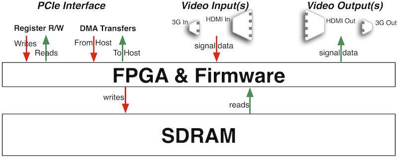
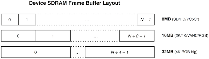
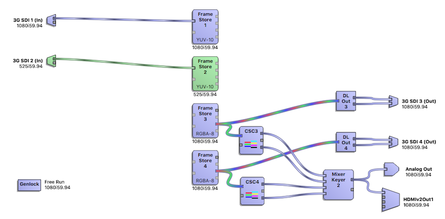
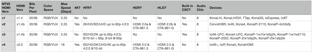
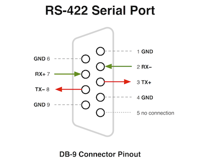

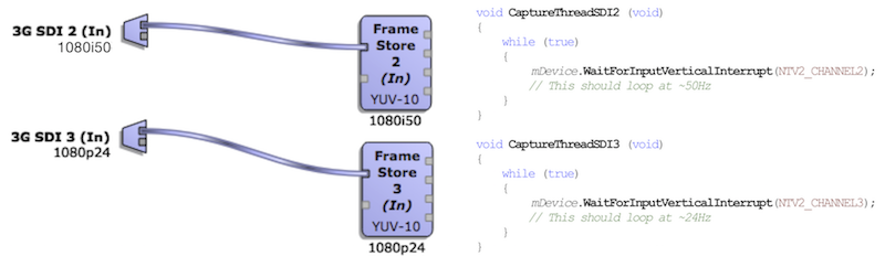
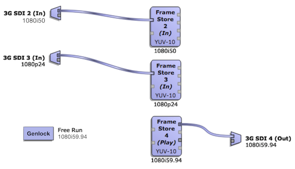
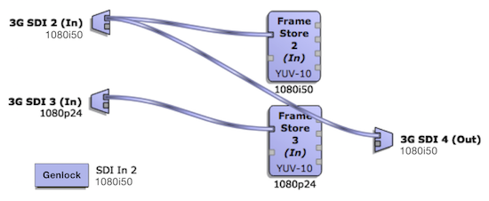
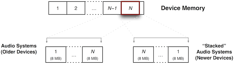
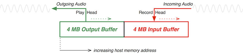
 1.8.14