Corvid OEM Boards
Io (Thunderbolt) Devices
Kona Boards
Legacy Devices
Breakout Boxes and Cables
Breakout Boxes and Cables
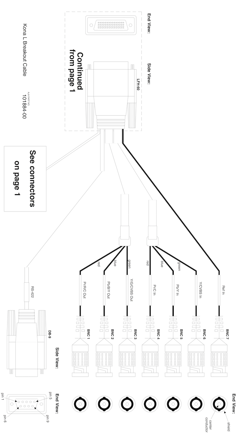
101884 Breakout Cable
The AJA 101884 Breakout Cable is designed to connect to the KONA LHe Plus and KONA LHi ingest/playout boards.
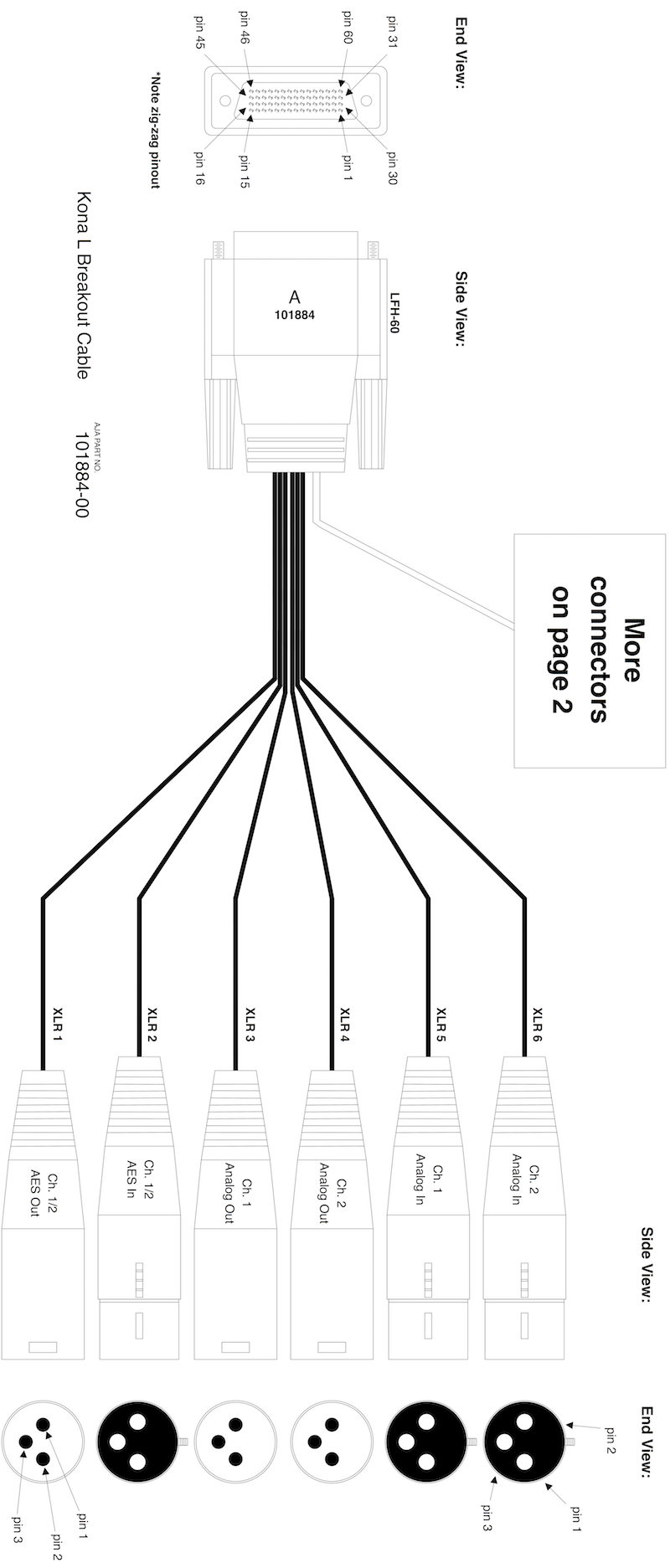
Pin Map
| Pin (LFH-60) | Function | Pin, Connector |
| 1 | GND | shield, BNC3 |
| 2 | Y/G/CVBS Out | center conductor, BNC3 |
| 3 | GND | shield, BNC2 |
| 4 | Pb/B/Y Out | center conductor, BNC2 |
| 5 | GND | shield, BNC1 |
| 6 | Pr/R/C Out | center conductor, BNC1 |
| 7 | GND | shield, BNC6 |
| 8 | Y/CVBS In | center conductor, BNC6 |
| 9 | GND | shield, BNC5 |
| 10 | Pb/Y In | center conductor, BNC5 |
| 11 | GND | shield, BNC4 |
| 12 | Pr/C In | center conductor, BNC4 |
| 13 | GND | shield, BNC7 |
| 14 | Reference In | center conductor, BNC7 |
| 15 | +5V | no connection |
| 16 | +5V | no connection |
| 17 | NC | no connection |
| 18 | GND | 1+4+6+9, DB-9 |
| 19 | GND | 1, XLR5 & XLR6 |
| 20 | S5 | no connection |
| 21 | GND | 1, XLR3 & XLR4 |
| 22 | S4 | no connection |
| 23 | GND | no connection |
| 24 | S3 | no connection |
| 25 | GND | 1, XLR2 |
| 26 | S2 | no connection |
| 27 | GND | no connection |
| 28 | S1 | no connection |
| 29 | GND | 1, XLR1 |
| 30 | S0 | no connection |
| 31 | AES Out 1/2+ | 2, XLR1 |
| 32 | AES Out 3/4+ | no connection |
| 33 | AES Out 5/6+ | no connection |
| 34 | AES Out 7/8+ | no connection |
| 35 | AES In 1/2+ | 2, XLR2 |
| 36 | AES In 3/4+ | no connection |
| 37 | AES In 5/6+ | no connection |
| 38 | AES In 7/8+ | no connection |
| 39 | Analog Out 1+ | 2, XLR3 |
| 40 | Analog Out 2+ | 2, XLR4 |
| 41 | Analog In 1+ | 2, XLR5 |
| 42 | Analog In 2+ | 2, XLR6 |
| 43 | RS-422 Tx+ | 3, DB-9 |
| 44 | RS-422 Rx+ | 7, DB-9 |
| 45 | S6 | no connection |
| 46 | S7 | no connection |
| 47 | RS-422 Rx- | 2, DB-9 |
| 48 | RS-422 Tx- | 8, DB-9 |
| 49 | Analog In 2- | 3, XLR6 |
| 50 | Analog In 1- | 3, XLR5 |
| 51 | Analog Out 2- | 3, XLR4 |
| 52 | Analog Out 1- | 3, XLR3 |
| 53 | AES In 7/8- | no connection |
| 54 | AES In 5/6- | no connection |
| 55 | AES In 3/4- | no connection |
| 56 | AES In 1/2- | 3, XLR2 |
| 57 | AES Out 7/8- | no connection |
| 58 | AES Out 5/6- | no connection |
| 59 | AES Out 3/4- | no connection |
Breakout Boxes and Cables
102953 Breakout Cable
The AJA 102953 Breakout Cable is designed to connect to the Corvid 22 and Corvid 24 ingest/playout boards.
Breakout Boxes and Cables
103226 Breakout Cable
The AJA 103226 Breakout Cable is designed to connect to the KONA 3G (Quad Mode) / KONA 3G (UFC Mode) and KONA 4 (Quad Mode) and KONA 4 (UFC Mode) ingest/playout boards.
Breakout Boxes and Cables
K3G-Box Breakout Box
This page describes the AJA K3G-Box Breakout Box, which can be connected to a KONA 3G or KONA 4 capture/playout boards.
- Front Panel
The left side of the front panel has BNC connectors for 16 input and output AES/EBU audio channels.
The center of the front panel has HDMI out, plus BNC connectors for each of the four SDI inputs/outputs, and BNCs for analog component video output.
The far right side of the front panel has connectors for Reference in & out, LTC In, LTC Out, UART 1, and RCA connectors for line-level outputs for audio channels 1 & 2.
- Rear Panel
These connectors tie the breakout box to the KONA 3G or KONA 4 board in the host computer (cable included with the box).
Breakout Boxes and Cables
KL-Box-LH Breakout Box
This page describes the AJA KL-Box-LH Breakout Box, which can be connected to a KONA LHe Plus capture/playout board.
- Front Panel
The far left side of the front panel has a group of XLR connectors for balanced analog audio input and output. The left two XLRs are balanced analog audio inputs. The right two XLRs are balanced analog audio outputs.
The center of the front panel has XLR and BNC connectors for (unbalanced) AES/EBU audio inputs & outputs.
Finally, on the right are BNCs for SDI In, SDI Out 1, and SDI Out 2; BNCs for reference in & out; BNCs for analog video in & out; one DB-9 connector for the RS-422 serial port; and twin RCAs for line-level audio channel 1 and 2 output.
- Rear Panel
These connectors tie the box to the KONA LHe Plus board in the host computer.
Breakout Boxes and Cables
KLHi-Box Breakout Box
This page describes the AJA KLHi-Box Breakout Box, which can be connected to a KONA LHi capture/playout board.
- Front Panel
The far left side of the front panel has a group of four XLR connectors for analog audio. The left two XLRs are balanced analog audio input channels. The right two XLRs are balanced analog audio output channels.
Next to the analog grouping is the AES/EBU audio group. Two XLRs are provided for two channels of AES/EBU (unbalanced) audio; one (female) for input, the other (male) for output. BNCs are provided for two channels of (unbalanced) audio, one input, and one output.
The center of the front panel has one HDMI input, one HDMI output, plus two BNC connectors, one for SDI input, the other for SDI output.
Toward the right side, there's the Reference Loop section with two BNCs, one for Reference in, the other for Reference out.
Next to that is the analog component video BNC group, inputs on top, outputs on the bottom.
Finally, on the far right side is the DB-9 RS-422 serial connector, and two RCA output connectors for line-level audio channels 1 and 2.
- Rear Panel
These connectors tie the box to the KONA LHi board in the host computer.
Corvid OEM Boards
Corvid, Corvid 3G
This page describes the Corvid (sometimes called the Corvid 1), and the Corvid 3G OEM video capture/playout boards.
- Note
- These products have been superceded by KONA 1 . See the Corvid 1 EOL Announcement and Corvid 3G EOL Announcement.
The Corvid 1 – identified by DEVICE_ID_CORVID1 – has one SDI input, one SDI output, one LTC input or output, and one RS-422 port. It can handle 8 or 10 bit video up to 720p60 and 1080p30.
The Corvid 3G – identified by DEVICE_ID_CORVID3G – has one SDI input, one SDI output, one LTC input, and one RS-422 port. It has a video processing module (mixer/keyer), and can handle 2K and 3Gb video formats.
The Corvid 3G Fiber looks very similar:
The connector layout is the same on all three boards: RS-422 serial on the far left; LTC in/out on the left, video input in the middle, and video output on the right.
- PCI Interface
- PCI device ID (Corvid): 0xDAFE
- PCI device ID (Corvid3G): 0xDB03
- Four-lane gen 1 PCI Express
- 2 DMA engines
- Legacy interrupt delivery (INTA# for all interrupts) — MSI not supported
- Inputs & Outputs
- 1 × SDI input
- 1 × SDI output
- 1 × reference input
- 1 × LTC input
- 1 × RS-422 serial port
- Frame Buffer
- 256 MB SDRAM
- 32 × 8MB frames
- 16 × 16MB frames for 2K (1080×2048), 1920×1080 VANC, and 16-bit RGB (Corvid 3G only)
- Audio
- 1 audio system
- 8 channels (max.) per audio system
- Audio system’s 8MB buffer memory starts at first byte of last frame
- Video Formats
- Supports most standard video formats.
- Does not support DVCPro HD or HDV.
- RGB on SDI inputs/outputs not supported.
- Ancillary Data
- Note
- A hardware color-space converter (CSC) can convert the input/output YCbCr SDI to/from RGB when using RGB buffer formats (Corvid 3G only).
- SDK Support
- Firmware
- Physical
- Size (W × D × H): 0.55" × 6.61" × 2.16" (14mm × 168mm × 55mm)
- Environment
- Safe Operating Temperature: 0°C to 40°C (32°F to 104°F)
- Operating Relative Humidity: 10-90% non-condensing
- Operating Altitude: under 3,000 meters (under 10,000 feet)
- Safe Storage Temperature (Power OFF): -40°C to 60°C (-40°F to 140°F)
Corvid OEM Boards
Corvid 22
This page describes the Corvid 22 capture/playout board. It’s identified by DEVICE_ID_CORVID22.
The Corvid 22 has two SDI inputs, two SDI outputs, plus a reference input. The connector on the far left is for the optional AJA 102953 breakout cable.
- PCI Interface
- PCI device ID: 0xDB01
- Four-lane gen 1 PCI Express
- 3 DMA engines
- Legacy interrupt delivery (INTA# for all interrupts) — MSI not supported
- Inputs & Outputs
- 2 × SDI inputs
- 2 × SDI outputs
- 1 × reference input
- 2 × RS-422 serial ports
- Frame Buffer
- 512 MB SDRAM
- 64 × 8MB frames
- 32 × 16MB frames for 2K (1080×2048), 1920×1080 VANC, and 16-bit RGB
- Audio
- 2 audio systems
- 16 channels (max.) per audio system
- First audio system’s 8MB buffer memory starts at first byte of last frame
- Video Formats
- Supports most standard video formats.
- Does not support DVCPro HD or HDV.
- RGB on SDI inputs/outputs not supported.
- Note
- A hardware color-space converter (CSC) can convert the input/output YCbCr SDI to/from RGB when using RGB buffer formats.
- Ancillary Data
- External Connectivity
- SDK Support
- Firmware
- https://sdksupport.aja.com/index.php?/Knowledgebase/Article/View/130/25
- Physical
- Size (W × D × H): 0.708" × 6.57" × 3.86" (18mm × 167mm × 98mm)
- Power: 12w (typ), 15w (max)
- Environment
- Safe Operating Temperature: 0°C to 40°C (32°F to 104°F)
- Operating Relative Humidity: 10-90% non-condensing
- Operating Altitude: under 3,000 meters (under 10,000 feet)
- Safe Storage Temperature (Power OFF): -40°C to 60°C (-40°F to 140°F)
- Additional Topics
102953 Breakout Cable
Corvid OEM Boards
Corvid 24
This page describes the Corvid 24 OEM capture/playout board, which features bypass relays on each SDI connector that can operate under software control or hardware control (using the built-in “watchdog” timer). Its four SDI connectors can programmatically be configured as inputs or outputs. It’s identified by DEVICE_ID_CORVID24.
- Note
- This board has been superseded by Corvid 44. See the EOL Announcement for details.
The Corvid24 has four bi-directional SDI connectors, plus a reference input. The connector on the far left is for the optional AJA 102953 Breakout Cable .
- PCI Interface
- PCI device ID: 0xDB09
- Four-lane gen 2 PCI Express
- 2 DMA engines
- Legacy interrupt delivery (INTA# for all interrupts) — MSI not supported
- Inputs & Outputs
- 4 × SDI bi-directional inputs/outputs (under software control)
- 1 × reference input
- 2 × RS-422 serial ports
- Frame Buffer
- 512 MB SDRAM
- 64 × 8MB frames
- 32 × 16MB frames for 2K (1080×2048), 1920×1080 VANC, and 16-bit RGB
- Audio
- 4 audio systems
- 16 channels (max.) per audio system
- First audio system’s 8MB buffer memory ends at the end of SDRAM
- Video Formats
- Supports most standard video formats.
- Does not support DVCPro HD or HDV.
- RGB on SDI inputs/outputs not supported.
- Note
- A hardware color-space converter (CSC) can convert the input/output YCbCr SDI to/from RGB when using RGB buffer formats.
- Ancillary Data
- External Connectivity
- Bypass Relays
In a typical facility a video signal may pass through many types of equipment before reaching its final destination. In the event that a device in this video path should fail, the disruption of the signal can be minimized by bypassing the faulty device.
The AJA Corvid24 board has relays on its SDI connectors that can perform this bypass function. One set of relays will bypass the SDI 1 and SDI 2 connectors, and the other set of relays will bypass connectors SDI 3 and SDI 4. The two sets of relays are independently controllable.
The relays may be switched directly by software, or they can be put under the control of a watchdog timer. The watchdog can be configured to switch the relays to bypass after a programmable time interval has elapsed. Software can prevent this by writing specific values to the watchdog before the time interval expires to indicate it is still functioning properly.
Users of the bypass relay feature will want to cable their systems with SDI 1 and SDI 3 as inputs, and SDI 2 and SDI 4 as outputs. Note that by default the Corvid24 firmware will configure SDI 1 and SDI 2 as inputs, and SDI 3 and SDI 4 as outputs. Because of this, during initialization user applications should use the CNTV2Card::SetSDITransmitEnable SDK call to set the correct direction of the SDI ports before taking the relays out of bypass.
- Hardware Jumpers
Two jumpers on the upper left of the component side of the Corvid24 enable or disable control of the bypass relays. The top jumper controls the bypass between SDI connectors 1 and 2, and the other between connectors 3 and 4. When a jumper is in the leftmost position, the corresponding bypass relays are disabled, and the SDI signals are connected to the logic on the board. This is the same routing as AJA boards without relays. When a jumper is in the rightmost position, control of the relay state is put under firmware control. In Figure 5 below, the connector 1 and 2 bypass (Jumper 1) is controlled by the firmware, and the connector 3 and 4 bypass (Jumper 2) is disabled.
The NTV2 SDK provides several functions for querying and/or controlling the bypass relays:
- SDK Support
- Firmware
- https://sdksupport.aja.com/index.php?/Knowledgebase/Article/View/131/25
- Physical
- Size (W × D × H): 0.708" × 6.57" × 3.86" (18mm × 167mm × 98mm)
- Power: 12w (typ), 15w (max)
- Environment
- Safe Operating Temperature: 0°C to 40°C (32°F to 104°F)
- Operating Relative Humidity: 10-90% non-condensing
- Operating Altitude: under 3,000 meters (under 10,000 feet)
- Safe Storage Temperature (Power OFF): -40°C to 60°C (-40°F to 140°F)
- Additional Topics
102953 Breakout Cable
Corvid OEM Boards
Corvid 44
This page describes the Corvid 44 OEM capture/playout board, which features four SDI connectors that can be programmatically configured as inputs or outputs. It’s identified by DEVICE_ID_CORVID44.
The Corvid44 has an RS-422 serial port, 4 × bi-directional SDI connectors, a reference/LTC input BNC, and a secondary LTC-only input connector on the board header.
BNC Version:
Low-Profile Version:
Fanless Version: (See important environmental note below.)
Low-Profile Fanless Version: (See important environmental note below.)
- PCI Interface
- PCI device ID: 0xEB0E
- Eight-lane gen 2 PCI Express
- 2 DMA engines
- Inputs & Outputs
- 4 × SDI bi-directional (under software control)
- 1 × reference/LTC input
- 1 × secondary LTC-only input (2-pin Molex connector on board header)
- 1 × RS-422 serial port (full-height board version has DB-9 connector)
- Frame Buffer
- 1GB SDRAM
- 128 × 8MB frames
- 64 × 16MB frames for 2K (1080×2048), 1920×1080 VANC, and 16-bit RGB
- Support for planar formats added in firmware rev 0xNN and SDK 14.0:
- Audio
- 4 audio systems
- 16 channels (max.) per audio system
- First audio system’s 8MB buffer memory ends at the end of SDRAM
- Video Formats
- Supports all SD, HD, 2K and 4K video formats, including 4Kp60.
- Multiple, independent video formats supported (provided all in same clock family).
- Does not support DVCPro HD or HDV.
- RGB on SDI inputs/outputs supported.
- 3GbA and 3GbB (dual-link) supported.
- SMPTE 425 2si mux supported
- Note
- A hardware color-space converter (CSC) can convert the input/output YCbCr SDI to/from RGB when using RGB buffer formats.
- Ancillary Data
- SDK Support
- Firmware
- https://sdksupport.aja.com/index.php?/Knowledgebase/Article/View/154/25
- Physical
- Size (W × D × H): 0.875" × 7.25" × 4.875" (22.23mm × 184.15mm × 123.83mm)
- Weight: 0.4 lb (0.2 kg)
- Power: 17w (typ), 19w (max)
- Environment
- Safe Operating Temperature: 0°C to 40°C (32°F to 104°F)
- Operating Relative Humidity: 10-90% non-condensing
- Operating Altitude: under 3,000 meters (under 10,000 feet)
- Safe Storage Temperature (Power OFF): -40°C to 70°C (-40°F to 158°F)
- Note
- The fanless version of this device requires airflow of 100LFM @25deg C or lower, and the host chassis must have a vented opening to the exterior, immediately adjacent to the PCIe shield (heatsink side), to permit 100LFM across the heatsink.
Corvid OEM Boards
Corvid 44 12G
This page describes the Corvid 44 12G OEM capture/playout board, which features four 12G SDI connectors that can be programmatically configured as inputs or outputs. It’s identified by these device identifiers:
The Corvid 44 12G has an RS-422 serial port, 4 × bi-directional 12G-SDI connectors, a reference/LTC input BNC, and a secondary LTC-only input connector on the board header.
Low-Profile Version:
This board is available with either active (fan) or passive cooling (no fan). (See environmental note below.)
- PCI Interface
- PCI device ID: 0xEB25
- Eight-lane gen 3 PCI Express
- 2 DMA engines
- Inputs & Outputs
- 4 × 12G-SDI bi-directional (under software control)
- 1 × reference/LTC input
- 1 × secondary LTC-only input (2-pin Molex connector on board header)
- 1 × RS-422 serial port (full-height board version has DB-9 connector)
- Frame Buffer
- 4GB SDRAM
- 512 × 8MB frames
- 256 × 16MB frames for 2K (1080×2048), 1920×1080 VANC, and 16-bit RGB
- Audio
- 4 audio systems
- 16 channels (max.) per audio system
- First audio system’s 8MB buffer memory ends at the end of SDRAM
- Video Formats
- Supports all SD, HD, 2K, 4K and UHD2 video formats (8K coming soon).
- Multiple, independent video formats supported (playout requires same clock family).
- SMPTE 425 2si mux supported
- Ancillary Data
- SDK Support
- Firmware
- Physical
- Size with Standard PCIe Bracket (W × D × H): 0.875" × 7.25" × 4.875" (22.23mm × 184.15mm × 123.83mm)
- Size with Low-Profile PCIe Bracket (W × D × H): 0.875" × 7.25" × 3.2" (22.23mm × 184.15mm × 81.28mm)
- Weight: 0.47 lb (0.21 kg)
- Power: 25w (typ), 32w (max)
- Environment
- Safe Operating Temperature: 0°C to 40°C (32°F to 104°F)
- Operating Relative Humidity: 10-90% non-condensing
- Operating Altitude: under 3,000 meters (under 10,000 feet)
- Safe Storage Temperature (Power OFF): -40°C to +70°C (-40° to +158°F)
- Note
- The fanless (passively-cooled) version of this device requires airflow of 150LFM @30°C or lower. Most host systems have enough circulating airflow, neighboring vent holes, and/or ability to increase the case fan speed as necessary, such that additional steps or precautions are not required. However, if adequate cooling is not being achieved, then removal of the adjacent PCIe bracket next to the heatsink (adjacent to the CRV44-12G) is an option.
Corvid OEM Boards
Corvid 88
This page describes the Corvid 88 OEM capture/playout board, which features eight SDI connectors that can be programmatically configured as inputs or outputs. It’s identified by DEVICE_ID_CORVID88.
The Corvid88 has eight bi-directional SDI connectors, plus a reference/LTC input.
Low-Profile Version:
Fanless Version: (See important environmental note below.)
Low-Profile Fanless Version: (See important environmental note below.)
- PCI Interface
- PCI device ID: 0xEB0D
- Eight-lane gen 2 PCI Express
- 2 DMA engines
- MSI is supported
- Inputs & Outputs
- 8 × SDI bi-directional (under software control)
- 1 × reference/LTC input
- 1 × secondary LTC-only input (2-pin Molex connector on board header)
- 1 × RS-422 serial port (full-height board version has DB-9 connector)
- Frame Buffer
- 1GB SDRAM
- 128 × 8MB frames
- 64 × 16MB frames for 2K (1080x2048), 1920x1080 VANC, and 16-bit RGB
- Audio
- 8 audio systems
- 16 channels (max.) per audio system
- 24-bit PCM, 48kHz sample rate, synchronous SDI embedded
- First audio system’s 8MB buffer memory ends at the end of SDRAM
- Video Formats
- Supports all SD, HD, 2K and 4K video formats, including 4Kp60.
- Multiple, independent video formats supported (provided all in same clock family).
- Does not support DVCPro HD or HDV.
- RGB on SDI inputs/outputs supported.
- 3GbA and 3GbB (dual-link) supported
- SMPTE 425 2si mux supported
- Note
- A hardware color-space converter (CSC) can convert the input/output YCbCr SDI to/from RGB when using RGB buffer formats.
- Ancillary Data
- Secondary LTC Input
The secondary LTC input connector is a 2-pin Molex (part number 22-05-3021) located on the top of the board next to the fan. It allows the input of analog LTC while the Reference/LTC input is connected to a reference source. When looking at the top edge of the board, the pin closest to the front (toward the SDI connectors) is electrical ground. The pin closest to the back of the board should carry the LTC signal.
- SDK Support
- Firmware
- https://sdksupport.aja.com/index.php?/Knowledgebase/Article/View/133/25
- Physical
- Size (W × D × H): 0.875" × 7.25" × 4.875" (22.23mm × 184.15mm × 123.83mm)
- Weight: 0.4 lb (0.2 kg)
- Power: 17 watts (typ), 19 watts (max)
- Environment
- Operating Temperature: 0°C to 40°C (32°F to 104°F)
- Operating Relative Humidity: 10-90% non-condensing
- Operating Altitude: under 3,000 meters (under 10,000 feet)
- Safe Storage Temperature (Power OFF): -40°C to 70°C (-40°F to 158°F)
- Note
- The fanless version of this device requires airflow of 100LFM @25deg C or lower, and the host chassis must have vented opening to the exterior, immediately adjacent to the PCIe shield (heatsink side), to permit 100LFM across the heatsink.
Corvid OEM Boards
Corvid HB-R
- Note
- This product was End-Of-Lifeʼd on 20JUL2020. See the official EOL notice.
This page describes the Corvid HB-R OEM capture board. It’s identified by DEVICE_ID_CORVIDHBR.
The HB-R provides a single RJ-45 HDBaseT connector that supplies power (up to 10 watts), ingests HDMI video (up to 4Kp60, 8-bit 4:2:0) and audio (up to 8 embedded audio channels), and includes bi-directional VISCA/RS-232 control. It was developed as an OEM ingest solution for AJA’s RovoCam and other HDBaseT camera devices.
- PCI Interface
- PCI device ID: 0xEB18
- Four-lane gen 2 PCI Express
- 2 DMA engines
- Inputs & Outputs
- 1 × RJ-45 HDBaseT input connector
- 1 × HDMI 1.4b full-time looped output
- Frame Buffer
- 512MB SDRAM
- 64 × 8MB frames
- 32 × 16MB frames for 2K (1080x2048), 1920x1080 VANC, and 16-bit RGB
- Audio
- 1 audio system
- 16 channels (max.) per audio system
- First audio system’s 8MB buffer memory ends at the end of SDRAM
- Video Formats
- Supports all SD, HD, 2K and 4K video formats, including 4Kp60 (no DVCPro HD or HDV).
- Note
- A hardware color-space converter (CSC) can convert the input YCbCr to RGB when using RGB buffer formats, or input RGB to YCbCr when using YUV buffer formats.
-
A hardware 4K down-converter can convert incoming 4K/UHD video to standard HD (1080) rasters.
- SDK Support
- Firmware
- https://sdksupport.aja.com/index.php?/Knowledgebase/Article/View/203/25
- Physical
- Size, without bracket (W × D × H): 0.7" × 6.7" × 2.7" (18mm × 170mm × 69mm)
- Bracket is standard full-height PCIe card size
- Conforms to PCIe Card Electromechanical Specification Rev 1.0A low-profile add-in card
- Power: 10-20V, 10W (typical, card only), 16W (typical, when powering RovoCam), 18W (max)
- Environment
- Safe Operating Temperature: 0°C to 40°C (32°F to 104°F)
- Operating Relative Humidity: 10-90% non-condensing
- Operating Altitude: under 3,000 meters (under 10,000 feet)
- Safe Storage Temperature (Power OFF): -40°C to 60°C (-40°F to 140°F)
Corvid OEM Boards
Corvid HEVC
This page describes the Corvid HEVC OEM capture/playout board, which features four SDI inputs to support real time, low-latency HEVC encoding up to 4Kp60. It’s identified by DEVICE_ID_CORVIDHEVC.
The Corvid HEVC has 4 × input SDI connectors and an LTC/reference input BNC.
- PCI Interface
- PCI device ID: 0xEB15
- Eight-lane gen 2 PCI Express
- 2 DMA engines
- Inputs
- 4 × 3G-SDI inputs
- 1 × LTC input
- Frame Buffer
- 1GB SDRAM
- 64 × 16MB frames for 2K (1080x2048), 1920x1080 VANC, and 16-bit RGB
- Audio
- 4 audio systems
- 16 channels (max.) per audio system
- First audio system’s 8MB buffer memory ends at the end of SDRAM
- Video Formats
- Supports all HD, 2K and 4K video formats, including 4Kp60.
- Multiple, independent video formats supported (provided all in same clock family).
- Does not support DVCPro HD or HDV.
- RGB on SDI inputs/outputs supported.
- 3GbA and 3GbB (dual-link) supported.
- SMPTE 425 2si mux supported
- Note
- A hardware color-space converter (CSC) can convert input YCbCr SDI to RGB when using RGB buffer formats.
- Ancillary Data
- SDK Support
- Firmware
- https://sdksupport.aja.com/index.php?/Knowledgebase/Article/View/172/25
- Physical
- Size, without bracket (W × D × H): 0.875" × 7.5" × 5" (22.23mm × 190.5mm × 127mm)
- Weight: 0.9 lb (0.4 kg)
- Power: Requires either PCIe bus power via graphics slot or ATX 6-pin from host power supply
- Environment
- Operating Temperature: 0°C to 40°C (32°F to 104°F)
- Operating Relative Humidity: 10-90% non-condensing
- Operating Altitude: under 3,000 meters (under 10,000 feet)
- Safe Storage Temperature (Power OFF): -40°C to 70°C (-40°F to 158°F)
Io (Thunderbolt) Devices
Io4K Plus
This page describes the Io4K Plus capture/playout device with standard Quad-Mode firmware, which supports 4K ingest or playout through a Thunderbolt III port. It’s identified by DEVICE_ID_IO4KPLUS.
- PCI Interface
- PCI device ID: 0xEB11
- Four-lane gen 3 PCI Express
- 2 DMA engines
- MSI supported
- 2 × Thunderbolt III connectors
- Inputs & Outputs
- 4 × SDI connectors
- Bi-directional in 3G mode (under software control), 4K/UHD input-only in 6G/12G mode
- Bi-directional 3G-SDI (under software control)
- Bi-directional in 3G mode (under software control), 4K/UHD output-only in 6G/12G mode
- Bi-directional 3G-SDI (under software control)
- 1 × 3G-SDI monitor output
- 1 × HDMI 2.0 input
- 1 × HDMI 2.0 output (supports HDR InfoFrame metadata and UHD/4Kp60 4:4:4)
- 1 × Reference/LTC input (Ref supports 1V analog color black, 2/4V composite sync, or 1V HD tri-level sync)
- 1 × LTC output
- 1 × RS-422 serial port
- 1 × Microphone input
- 1 × DB-25 connector for audio (8 channels in, or 8 channels out, or 4-in/4-out)
- Frame Buffer
- 2GB SDRAM
- 256 × 8MB frames
- 128 × 16MB frames for 2K (1080x2048), 1920x1080 VANC, and 16-bit RGB
- Audio
- 5 audio systems, 1 reserved for Mic input
- 16 channels (max.) per audio system
- 24-bit D/A 48kHz balanced analog audio XLRs (requires breakout cable):
- 8-channels input-only
- 8-channels output-only
- 4-channel input and 4-channel output
- Audio I/O to/from HDMI supports 2 or 8 audio channels
- First audio system’s 8MB buffer memory ends at the end of SDRAM
- Video Formats
- Supports all SD, HD, 2K and 4K video formats, including 4Kp60.
- Multiple, independent video formats supported (provided all in same clock family).
- DVCPro HD and HDV not supported with Quad firmware.
- RGB on SDI inputs/outputs supported.
- 3GbA and 3GbB (dual-link) supported.
- SMPTE 425 2si mux supported
- Note
- A hardware color-space converter (CSC) can convert the input/output YCbCr SDI to/from RGB when using RGB buffer formats.
- Ancillary Data
- Physical
- Size (W × D × H): 8.74" × 8.11" × 1.65" (222mm × 206mm × 42mm)
- Weight: 3.4 lb (1.5 kg)
- Power: 30W (typ), 33W (max), 70W max with USB-C power delivery to downstream devices
- Environment
- Operating Temperature: 0°C to 40°C (32°F to 104°F)
- Operating Relative Humidity: 10-90% non-condensing
- Operating Altitude: under 3,000 meters (under 10,000 feet)
- Safe Storage Temperature (Power OFF): -40°C to 60°C (-40°F to 140°F)
- SDK Support
- Firmware
- https://sdksupport.aja.com/index.php?/Knowledgebase/Article/View/io4k-plus-firmware
Io (Thunderbolt) Devices
Io4K (Quad Mode)
This page describes the Io4K capture/playout device with Quad-Mode firmware, which supports 4K ingest or playout through a Thunderbolt II port. It can be “flashed” with different firmware to become a 2-channel device (see Io4K (UFC Mode)). It’s identified by DEVICE_ID_IO4K.
- Note
- This product has been superceded by Io4K Plus. See the EOL Announcement for details.
- PCI Interface
- PCI device ID: 0xEB07
- Four-lane gen 2 PCI Express
- 2 DMA engines
- MSI supported
- 2 × Thunderbolt II connectors
- Inputs & Outputs
- 4 × SDI bi-directional (under software control)
- 1 × SDI monitor output
- 1 × HDMI 2.0 input
- 1 × HDMI output (HDMI v2.0a subset with v1.4 connection, to support HDR InfoFrame metadata and UHD/4K@60 4:2:0 YUV)
- 1 × Reference/LTC input
- 1 × LTC output
- 1 × RS-422 serial port
- Frame Buffer
- 888MB SDRAM
- 111 × 8MB frames
- 55 × 16MB frames for 2K (1080x2048), 1920x1080 VANC, and 16-bit RGB
- Audio
- 4 audio systems
- 16 channels (max.) per audio system
- First audio system’s 8MB buffer memory ends at the end of SDRAM
- Video Formats
- Supports all SD, HD, 2K and 4K video formats, including 4Kp60.
- Multiple, independent video formats supported (provided all in same clock family).
- DVCPro HD and HDV not supported with Quad firmware.
- RGB on SDI inputs/outputs supported.
- 3GbA and 3GbB (dual-link) supported.
- SMPTE 425 2si mux supported
- Note
- A hardware color-space converter (CSC) can convert the input/output YCbCr SDI to/from RGB when using RGB buffer formats.
- Ancillary Data
- Physical
- Size (W × D × H): 8.74" × 7.09" × 1.65" (222mm × 180mm × 42mm)
- Weight: 3.1 lb (1.5 kg)
- Power: 23W (typ), 28W (max)
- NOTE: Power supply to Thunderbolt ports can cause power draw to reach 58W
- Environment
- Operating Temperature: 0°C to 35°C (32°F to 95°F)
- Operating Relative Humidity: 10-90% non-condensing
- Operating Altitude: under 3,000 meters (under 10,000 feet)
- Safe Storage Temperature (Power OFF): -40°C to 60°C (-40°F to 140°F)
- SDK Support
- Firmware
- https://sdksupport.aja.com/index.php?/Knowledgebase/Article/View/io4k-firmware
Io (Thunderbolt) Devices
Io4K (UFC Mode)
This page describes the Io4K capture/playout device with UFC firmware, which supports high frame-rate ingest or playout through a Thunderbolt II port. It can be “flashed” with different firmware to become a 4-channel device (see Io4K (Quad Mode)). It’s identified by DEVICE_ID_IO4KUFC.
- Note
- This product has been superceded by Io4K Plus. See the EOL Announcement for details.
- PCI Interface
- PCI device ID: 0xEB07
- Four-lane gen 2 PCI Express
- 2 DMA engines
- MSI supported
- 2 × Thunderbolt II connectors
- Inputs & Outputs
- 2 × SDI inputs
- 2 × SDI outputs
- 1 × SDI monitor output
- 1 × HDMI 2.0 input
- 1 × HDMI output (HDMI v2.0a subset with v1.4 connection, to support HDR InfoFrame metadata and UHD/4K@60 4:2:0 YUV)
- 1 × Reference/LTC input
- 1 × LTC output
- 1 × RS-422 serial port
- Frame Buffer
- 888MB SDRAM
- 111 × 8MB frames
- 55 × 16MB frames for 2K (1080x2048), 1920x1080 VANC, and 16-bit RGB
- Audio
- 2 audio systems
- 16 channels (max.) per audio system
- First audio system’s 8MB buffer memory ends at the end of SDRAM
- Video Formats
- Supports all SD, HD, and 2K video formats, including HFR.
- Supports DVCPro HD and HDV.
- RGB on SDI inputs/outputs supported.
- 3GbA and 3GbB (dual-link) supported.
- SMPTE 425 2si mux supported
- Note
- A hardware color-space converter (CSC) can convert the input/output YCbCr SDI to/from RGB when using RGB buffer formats.
- Ancillary Data
- Physical
- Size (W × D × H): 8.74" × 7.09" × 1.65" (222mm × 180mm × 42mm)
- Weight: 3.1 lb (1.5 kg)
- Power: 23W (typ), 28W (max)
- NOTE: Power supply to Thunderbolt ports can cause power draw to reach 58W
- Environment
- Operating Temperature: 0°C to 35°C (32°F to 95°F)
- Operating Relative Humidity: 10-90% non-condensing
- Operating Altitude: under 3,000 meters (under 10,000 feet)
- Safe Storage Temperature (Power OFF): -40°C to 60°C (-40°F to 140°F)
- SDK Support
- Firmware
- https://sdksupport.aja.com/index.php?/Knowledgebase/Article/View/io4k-firmware
Io (Thunderbolt) Devices
Io Express
This page describes the IoExpress capture/playout device. It’s identified by DEVICE_ID_IOEXPRESS.
The IoExpress supports 8/10-bit single-channel SD/HD SDI or HDMI ingest/playout through a PCMCIA connector.
- PCI Interface
- PCI device ID: 0xDB00
- Four-lane gen 2 PCI Express
- 2 DMA engines
- Legacy interrupt delivery (INTA# for all interrupts) — MSI not supported
- Inputs & Outputs
- 1 × 1.5G SDI input
- 1 × 1.5G SDI output
- 1 × HDMI input
- 1 × HDMI output
- 1 × reference/LTC input
- 1 × LTC output
- 1 × RS-422 serial port
- 1 × analog component video output
- Frame Buffer
- 256 MB SDRAM
- 32 × 8MB frames
- 16 × 16MB frames for 2K (1080×2048), 1920×1080 VANC (YCbCr only)
- Audio
- 1 audio system
- 8 channels (max.) per audio system
- Audio system’s 8MB buffer memory starts at first byte of last frame
- Video Formats
- Supports most standard SD and HD video formats.
- Does not support DVCPro HD or HDV.
- RGB is not supported.
- Ancillary Data
- SDK Support
- Firmware
- https://sdksupport.aja.com/index.php?/Knowledgebase/Article/View/135/25
Io (Thunderbolt) Devices
Io IP
This page describes the Io IP device. It can be "flashed" with different firmware to support one of many different video-over-IP standards. It's a flexible hardware device that can support, via firmware upgrades, many IP protocols including SMPTE ST-2022, SMPTE ST-2110 and more. It’s identified by one of these device identifiers:
- Note
- This board has been discontinued. See the EOL Announcement for details.
Io IP has two 10GigE SFP cages for multichannel input and/or output, enabling effective IP video reception, delivery or both.
- PCI Interface
- PCI device ID: 0xEB1B
- Four-lane gen 3 PCI Express
- 2 DMA engines
- MSI supported
- 2 × Thunderbolt III connectors
- Inputs & Outputs
- 2 × bi-directional 10GbE SFP+ TCP/IP cages, represented in firmware as 4 × virtual 3G-SDI bi-directional SDI spigots
- SMPTE 2022-6 supported for input & output, up to 4 streams of SD or HD each with 16 audio channels and metadata
- 1 × HDMI 1.4 output (8-channel embedded audio support, no HDCP support)
- 1 × reference input
- Frame Buffer
- 2GB SDRAM
- 256 × 8MB frames
- 128 × 16MB frames for 2K (1080×2048), 1920×1080 VANC, and 16-bit RGB
- Audio
- 2 audio systems
- 16 channels (max.) per audio system
- First audio system’s 8MB buffer memory ends at the end of SDRAM
- Video Formats
- Supports all standard video formats, plus 2K and 4K/UHD formats, and 4Kp60.
- Note
- 4 × hardware color-space converters (CSCs) can convert the input/output YCbCr to/from RGB when using RGB buffer formats.
- Ancillary Data
- Video Processing
- 2 × independent Mixer/Keyer widgets, each with its own Mix Coefficient
- Can mix keys on and off
- Can differentiate between shaped and unshaped video
- 2 × 2D LUTs
- Configuration
- The NTV2 JSON Setup Demo demo application shows how to software-configure the SFPs.
- Note that the Io IP has a MicroBlaze processor that must be booted when power is applied to the board, so it won't respond to configuration changes for a minute or two. To detect when the MicroBlaze is running, and thus when the SFPs can be configured, poll CNTV2DriverInterface::IsDeviceReady until it returns
true.
- SDK Support
- Firmware
-
- Physical
- Size (W × D × H): 0.75" × 8.25" × 5.0" (19.05mm × 209.55mm × 127mm)
- Weight: 0.7 lb (0.4 kg)
- Power: 25W (typ), 27W (max)
- Environment
- Safe Operating Temperature: 0°C to 40°C (32°F to 104°F)
- Operating Relative Humidity: 10-90% non-condensing
- Operating Altitude: under 3,000 meters (under 10,000 feet)
- Safe Storage Temperature (Power OFF): -40°C to 60°C (-40°F to 140°F)
Io (Thunderbolt) Devices
IoX3
This page describes the IoX3 Thunderbolt-3 capture/playout device. It’s identified by DEVICE_ID_IOX3.
- PCI Interface
- PCI device ID: 0xEB27
- Four-lane gen 2 PCI Express
- 2 DMA engines
- MSI interrupt delivery
- 2 × Thunderbolt-3 connectors
- Inputs & Outputs
- 4 × SDI inputs
- 4 × SDI outputs
- 1 × HDMI input
- 1 × HDMI output
- 1 × DB-25 connector for analog audio (8 channels in, or 8 channels out, or 4-in/4-out)
- 1 × Reference/LTC input
- 1 × LTC output
- 1 × RS-422 serial port
- Frame Buffer
- 1GB SDRAM (64MB reserved for UFC)
- 128 × 8MB frames
- 64 × 16MB frames for 2K (1080×2048), 1920×1080 VANC, and 16-bit RGB
- 32 × 32MB frames for UHD/4K
- Audio
- 4 audio systems
- 16 channels (max.) per audio system
- First audio system’s 8MB buffer memory ends at the end of SDRAM
- 24-bit D/A 48kHz balanced analog audio XLRs (requires breakout cable):
- 8-channels input-only
- 8-channels output-only
- 4-channel input and 4-channel output
- Video Formats
- SD:
- HD:
- 1080p 23.98, 24, 25, 29.97, 30, 47.95, 48, 50, 59.94, 60
- 1080PsF 23.98, 24, 25, 29.97, 30
- 1080i 50, 59.94, 60
- 720p 50, 59.94, 60
- 2K:
- 2048×1080p 23.98, 24, 25, 29.97, 30, 47.95, 48, 50, 59.94, 60
- 2048×1080PsF 23.98, 24, 25, 29.97, 30
- Note
- A hardware color-space converter (CSC) can convert the input/output YCbCr SDI to/from RGB when using RGB buffer formats.
- Ancillary Data
- Power Dissipation
- Video Processing
- 2 independent Mixer/Keyers, each with its own Mix Coefficient
- Can mix keys on and off
- Can differentiate between shaped and unshaped video
- SDK Support
- Firmware
- TBD https://sdksupport.aja.com/index.php?/Knowledgebase/List/Index/25
If, after a firmware update, the IoX3 fails to be recognized by the host:
- Be sure power is applied and the power switch is lighted.
- Be sure a good Thunderbolt cable is being used.
- Be sure the AJA driver software is installed and able to be loaded.
If the IoX3 still fails to be recognized, it may be that its main firmware image is corrupt. To force the IoX3 to load its fail-safe firmware:
- Be sure the IoX3’s power cord is connected to a known-good power source.
- Have a known-good Thunderbolt cable connected on only one end (either to the IoX3, or the host).
- Press the fail-safe button in the IoX3 by inserting an unbent paperclip lead into the hole shown in the photo (below).
- While the fail-safe button is pressed, connect the free end of the Thunderbolt cable to the IoX3 or host, as appropriate.
- When the IoX3 lights up, release the fail-safe button.
If the IoX3 is recognized by the host OS and AJA software, try re-flashing the firmware. If it’s still not recognized, you should contact AJA Support.
- Environment
- Safe Operating Temperature: 0°C to 40°C (32°F to 104°F)
- Operating Altitude: under 3,000 meters (under 10,000 feet)
- Safe Storage Temperature (Power OFF): -40°C to 60°C (-40°F to 140°F)
Io (Thunderbolt) Devices
IoXT
This page describes the IoXT Thunderbolt-based capture/playout device. It’s identified by DEVICE_ID_IOXT.
- Note
- This board has been superseded by IoX3. See the EOL Announcement for details.
- PCI Interface
- PCI device ID: 0xDB06
- Four-lane gen 2 PCI Express
- 2 DMA engines
- Legacy and MSI interrupt delivery supported
- 2 × Thunderbolt I connectors
- Inputs & Outputs
- 2 × SDI inputs
- 2 × SDI outputs
- 1 × HDMI input
- 1 × HDMI output
- 1 × analog component video output
- 1 × Reference/LTC input
- 1 × LTC output
- 1 × RS-422 serial port
- Frame Buffer
- 256MB SDRAM (64MB reserved for UFC, 192MB for frame storage)
- 32 × 8MB frames
- 16 × 16MB frames for 2K (1080×2048), 1920×1080 VANC, and 16-bit RGB
- Audio
- 2 audio systems
- 16 channels (max.) per audio system
- First audio system’s 8MB buffer memory ends at the end of SDRAM
- Video Formats
- Supports most standard SD, HD, and 2K video formats.
- RGB on SDI inputs/outputs not supported.
- Supports DVCPro HD and HDV.
- Note
- A hardware color-space converter (CSC) can convert the input/output YCbCr SDI to/from RGB when using RGB buffer formats.
- Ancillary Data
- Power Dissipation
- Video Processing
- 2 independent Mixer/Keyers, each with its own Mix Coefficient
- Can mix keys on and off
- Can differentiate between shaped and unshaped video
- SDK Support
- Firmware
- https://sdksupport.aja.com/index.php?/Knowledgebase/Article/View/136/25
If, after a firmware update, the IoXT fails to be recognized by the host:
- Be sure power is applied and the power switch is lighted.
- Be sure a good Thunderbolt cable is being used.
- Be sure the AJA driver software is installed and able to be loaded.
If the IoXT still fails to be recognized, it may be that its main firmware image is corrupt. To force the IoXT to load its fail-safe firmware:
- With the IoXT’s power cord connected, and a known-good Thunderbolt cable connected from IoXT to host, and with the host powered-on and awake…
- Press the fail-safe button in the IoXT by inserting an unbent paperclip lead into the hole next to the power button (see photo below).
- While the fail-safe button is pressed, press the IoXT’s power button. When it lights up, release both the power button and fail-safe button.
If the IoXT is recognized by the host OS and AJA software, you may try re-flashing the firmware. If it’s still not recognized, you should contact AJA Support.
- Environment
- Safe Operating Temperature: 0°-40°C (32°F-104°F)
- Operating Altitude: under 3,000 meters (under 10,000 feet)
Kona Boards
KONA 1
This page describes the KONA 1 capture/playout board. It’s identified by DEVICE_ID_KONA1.
The KONA 1 has three BNC connectors:
- Reference/LTC input (nearest the RS422 connector);
- Input SDI (middle connector);
- Output SDI.
- PCI Interface
- PCI device ID: 0xEB23
- Gen 2 × 1 PCIe
- 2 DMA engines
- MSI interrupt delivery supported
- Inputs & Outputs
- 1 × 3G-SDI input
- 1 × 3G-SDI output
- 1 × reference/LTC input
- 1 × RS-422 serial port
- Frame Buffer
- 1 GB SDRAM
- 128 × 8MB frames
- 64 × 16MB frames for 2K, HD VANC, and 16-bit RGB
- Audio
- 2 audio systems
- 16 audio channels (max.) per audio system
- First audio system’s 8MB buffer memory ends at the end of SDRAM
- Video Formats
- Supports all SD, HD and 2K formats up to 60fps.
- Note
- A hardware color-space converter (CSC) can convert the input/output YCbCr SDI to/from RGB when using RGB buffer formats.
- Ancillary Data
- Video Processing
- 1 Mixer/Keyer widget
- Can mix keys on and off
- Can differentiate between shaped and unshaped video
- SDK Support
- Firmware
- https://sdksupport.aja.com/index.php?/Knowledgebase/Article/View/202/25
- Physical
- Size (W × D × H): 0.55" × 6.61" × 2.16" (14mm × 168mm × 55mm)
- Weight: TBD
- Environment
- Safe Operating Temperature: 0°C to 40°C (32°F to 104°F)
- Operating Relative Humidity: 10-90% non-condensing
- Operating Altitude: under 3,000 meters (under 10,000 feet)
- Safe Storage Temperature (Power OFF): -40°C to 60°C (-40°F to 140°F)
Kona Boards
KONA 3G (Quad Mode)
This page describes the KONA 3G capture/playout board in its 4-channel mode of operation. It can be “flashed” with different firmware to become a 2-channel device (see KONA 3G (UFC Mode)). It’s identified by DEVICE_ID_KONA3GQUAD.
- Note
- This board has been superseded by KONA 4 (Quad Mode). See the EOL Announcement for details.
The KONA 3G has a breakout connector on the far left, followed by the HDMI output, then the four SDI connectors. In quad mode operation, the SDI connectors are bidirectional, and can be configured as inputs or outputs under software control.
- PCI Interface
- PCI device ID: 0xDB04
- Four-lane gen 2 PCI Express
- 2 DMA engines
- Legacy interrupt delivery (INTA# for all interrupts) — MSI not supported
- Inputs & Outputs
- 4 × SDI bi-directional (under software control)
- 1 × HDMI output
- 1 × analog component video output
- 2 × reference/LTC inputs
- 2 × LTC outputs
- 2 × RS-422 serial ports
- Frame Buffer
- 512 MB SDRAM
- 64 × 8MB frames
- 32 × 16MB frames for 2K (1080×2048), 1920×1080 VANC, and 16-bit RGB
- Audio
- 4 audio systems
- 16 channels (max.) per audio system
- 16 channels (max.) of AES audio
- First audio system’s 8MB buffer memory ends at the end of SDRAM
- AES audio inputs support asynchronous audio, 32Hz-96kHz, sample-rate converted to 48kHz
- Video Formats
- Supports all standard video formats, plus 2K and 4K formats (but not UHD, and not 4Kp60).
- Note
- A hardware color-space converter (CSC) can convert the input/output YCbCr SDI to/from RGB when using RGB buffer formats.
- Ancillary Data
- Video Processing
- 2 independent Mixer/Keyer widgets, each with its own Mix Coefficient
- Can mix keys on and off
- Can differentiate between shaped and unshaped video
- External Connectivity
- SDK Support
- Firmware
- https://sdksupport.aja.com/index.php?/Knowledgebase/Article/View/140/25
Kona Boards
KONA 3G (UFC Mode)
This page describes the KONA 3G capture/playout board in its 2-channel mode of operation. It can be “flashed” with different firmware to become a 4-channel device (see KONA 3G (Quad Mode)). It’s identified by DEVICE_ID_KONA3G.
- Note
- This board has been superseded by KONA 4 (UFC Mode). See the EOL Announcement for details.
The KONA 3G has a breakout connector on the far left, followed by the HDMI output, then the four SDI connectors. In normal operation, SDI connectors 1 and 2 are inputs; connectors 3 and 4 are outputs.
- PCI Interface
- PCI device ID: 0xDB02
- Four-lane gen 2 PCI Express
- 2 DMA engines
- Legacy interrupt delivery (INTA# for all interrupts) — MSI not supported
- Inputs & Outputs
- 2 × SDI inputs
- 2 × SDI outputs
- 1 × HDMI output
- 1 × analog component video output
- 2 × reference/LTC inputs
- 2 × LTC outputs
- 2 × RS-422 serial ports
- Frame Buffer
- 512 MB SDRAM
- 64 × 8MB frames
- 32 × 16MB frames for 2K (1080×2048), 1920×1080 VANC, and 16-bit RGB
- Audio
- 2 audio systems
- 16 channels (max.) per audio system
- 16 channels (max.) of AES audio
- First audio system’s 8MB buffer memory ends at the end of SDRAM
- AES audio inputs support asynchronous audio, 32Hz-96kHz, sample-rate converted to 48kHz
- Video Formats
- Supports all standard video formats (except 4K/UHD).
- Supports DVCPro HD and HDV.
- Note
- A hardware color-space converter (CSC) can convert the input/output YCbCr SDI to/from RGB when using RGB buffer formats.
- Ancillary Data
- Video Processing
- 2 independent Mixer/Keyer widgets, each with its own Mix Coefficient
- Can mix keys on and off
- Can differentiate between shaped and unshaped video
- External Connectivity
- SDK Support
- Firmware
- https://sdksupport.aja.com/index.php?/Knowledgebase/Article/View/138/25
Kona Boards
KONA 4 (Quad Mode)
This page describes the KONA 4 capture/playout board in its 4-channel mode of operation. It can be “flashed” with different firmware to become a 2-channel device (see KONA 4 (UFC Mode)). It’s identified by DEVICE_ID_KONA4.
The KONA 4 has a breakout connector on the far left, followed by the HDMI output, then the four SDI connectors. In quad mode operation, the SDI connectors are bidirectional, and can be configured as inputs or outputs under software control.
- PCI Interface
- PCI device ID: 0xEB0B
- Four-lane gen 2 PCI Express
- 2 DMA engines
- Legacy and MSI interrupt delivery supported
- Inputs & Outputs
- 4 × SDI bi-directional (under software control)
- 1 × HDMI output (HDMI v2.0a subset with v1.4 connection, to support HDR InfoFrame metadata and UHD/4K@60 4:2:0 YUV)
- 1 × analog component video output
- 2 × reference/LTC inputs
- 2 × LTC outputs
- 1 × RS-422 serial port
- Frame Buffer
- 888 MB SDRAM
- 111 × 8MB frames
- 55 × 16MB frames for 2K (1080×2048), 1920×1080 VANC, and 16-bit RGB
- Audio
- 4 audio systems
- 16 channels (max.) per audio system
- 16 channels (max.) of AES audio
- First audio system’s 8MB buffer memory ends at the end of SDRAM
- AES audio inputs support asynchronous audio, 32Hz-96kHz, sample-rate converted to 48kHz
- Video Formats
- Supports all standard video formats, plus 2K, 4K and UHD formats, including 4Kp60.
- Note
- A hardware color-space converter (CSC) can convert the input/output YCbCr SDI to/from RGB when using RGB buffer formats.
- Ancillary Data
- Video Processing
- 2 independent Mixer/Keyer widgets, each with its own Mix Coefficient
- Can mix keys on and off
- Can differentiate between shaped and unshaped video
- External Connectivity
- SDK Support
- Firmware
- https://sdksupport.aja.com/index.php?/Knowledgebase/Article/View/137/25
- Physical
- Size (W × D × H): 0.75" × 8.25" × 5.0" (19.05mm × 209.55mm × 127mm)
- Weight: 0.7 lb (0.4 kg)
- Environment
- Safe Operating Temperature: 0°C to 40°C (32°F to 104°F)
- Operating Relative Humidity: 10-90% non-condensing
- Operating Altitude: under 3,000 meters (under 10,000 feet)
- Safe Storage Temperature (Power OFF): -40°C to 60°C (-40°F to 140°F)
Kona Boards
KONA 4 (UFC Mode)
This page describes the KONA 4 capture/playout board in its 2-channel mode of operation. It can be “flashed” with different firmware to become a 4-channel device (see KONA 4 (Quad Mode)). It’s identified by DEVICE_ID_KONA4UFC.
The KONA 4 has a breakout connector on the far left, followed by the HDMI output, then the four SDI connectors. In UFC mode operation, SDI connectors 1 and 2 are inputs; connectors 3 and 4 are outputs.
- PCI Interface
- PCI device ID: 0xEB0C
- Four-lane gen 2 PCI Express
- 2 DMA engines
- Legacy and MSI interrupt delivery supported
- Inputs & Outputs
- 2 × SDI inputs
- 2 × SDI outputs
- 1 × HDMI output (HDMI v2.0a subset with v1.4 connection, to support HDR InfoFrame metadata and UHD/4K@60 4:2:0 YUV)
- 1 × analog component video output
- 2 × reference/LTC inputs
- 2 × LTC outputs
- 1 × RS-422 serial port
- Frame Buffer
- 888 MB SDRAM
- 111 × 8MB frames
- 55 × 16MB frames for 2K (1080×2048), 1920×1080 VANC, and 16-bit RGB
- Audio
- 2 audio systems
- 16 channels (max.) per audio system
- 16 channels (max.) of AES audio
- First audio system’s 8MB buffer memory ends at the end of SDRAM
- AES audio inputs support asynchronous audio, 32Hz-96kHz, sample-rate converted to 48kHz
- Video Formats
- Supports all standard video formats (except 4K/UHD).
- Supports DVCPro HD and HDV.
- Note
- A hardware color-space converter (CSC) can convert the input/output YCbCr SDI to/from RGB when using RGB buffer formats.
- Ancillary Data
- Video Processing
- 2 independent Mixer/Keyer widgets, each with its own Mix Coefficient
- Can mix keys on and off
- Can differentiate between shaped and unshaped video
- External Connectivity
- SDK Support
- Firmware
- https://sdksupport.aja.com/index.php?/Knowledgebase/Article/View/185/25
- Physical
- Size (W × D × H): 0.75" × 8.25" × 5.0" (19.05mm × 209.55mm × 127mm)
- Weight: 0.7 lb (0.4 kg)
- Environment
- Safe Operating Temperature: 0°C to 40°C (32°F to 104°F)
- Operating Relative Humidity: 10-90% non-condensing
- Operating Altitude: under 3,000 meters (under 10,000 feet)
- Safe Storage Temperature (Power OFF): -40°C to 60°C (-40°F to 140°F)
Kona Boards
KONA 5
This page describes the KONA 5 capture/playout board. It has two different firmware personalities:
- DEVICE_ID_KONA5 — “retail” personality, similar to the Io4K Plus (4 × 3G FrameStores, one 12G/6G in & out);
- DEVICE_ID_KONA5_8K — “OEM” personality, with all-new 12G FrameStore architecture. The specifications on this page reflect this firmware.
- Up to 8K YUV or RGB in/out
- No CSCs, no Mixer/Keyers, no audio mixer
- DEVICE_ID_KONA5_8KMK — Another “OEM” personality for the new 12G FrameStore architecture.
- Up to 8K YUV in/out
- Up to 4K using CSCs & mixer/keyers
- No audio mixer
The KONA 5 has a breakout connector on the top, followed by the HDMI output, then four 12G SDI connectors and a reference input connector. The SDI connectors are bidirectional, and can be configured as inputs or outputs under software control.
- KONA-5-R0 — ATX Power, cables included (for retail)
- KONA-5-R0-S00 — ATX Power, no cables included (OEM)
- KONA-5-R0-S01 — PCIe Power, cables included (OEM)
- KONA-5-R0-S02 — PCIe Power, no cables included (OEM)
- PCI Interface
- PCI device ID: 0xEB1F
- 8-lane gen 3 PCI Express
- 2 DMA engines
- MSI interrupt delivery
- Inputs & Outputs
- 4 × SDI connectors, bi-directional (under software control)
- 12G SDI, SMPTE 2082, 12/10/8-bit
- 6G SDI, SMPTE 2081, 10/8-bit
- 3G SDI, SMPTE 259/292/296/424, 12/10/8-bit
- 1.5G SDI:
- SMPTE 372M, Dual-Link HD 4:4:4 (2 × BNCs), 12/10/8-bit
- SMPTE 292M, Single-Link 4:2:2 (1 × BNC), 10/8-bit
- 1 × HDMI v2.0 output
- 30/36-bpp, RGB/YUV, 6-Gbps per color component
- 4K/UHD/2K/HD/SD + HFR up to 60p 4:2:2, 10/8-bit
- HDR10 support — HDR InfoFrame metadata, compatible with HDMI 2.0a/CTA-861.3
- HLG support — compatible with HDMI 2.0b/CTA-861-G
- 1 × Reference input (via 1 × HD-BNC at PCIe bracket)
- Analog Color Black (1V) or…
- Composite Sync (2V or 4V) or…
- HD Tri-Level Sync (1V)
- Reference input is terminated into 75Ω when Genlock set to NTV2_REFERENCE_EXTERNAL
- 1 × LTC output (via 1 × HD-BNC on Breakout Cable)
- 1 × LTC inputs — use one of:
- 1 × HD-BNC on Breakout Cable
- 1 × HD-BNC at PCIe bracket
- 2-pin header on PCIe card
- 1 × RS-422 serial port, Sony 9-pin protocol (via Breakout Cable)
- Frame Buffer
- 4GB SDRAM
- 512 × 8MB frames
- 256 × 16MB frames
- 128 × 32MB frames
- Audio
- 4 audio systems + Mixer audio system
- 16 channels (max.) per audio system
- 16 channels (max.) of AES audio
- First audio system’s 8MB buffer memory ends at the end of SDRAM
- AES audio inputs support asynchronous audio, 32Hz-96kHz, sample-rate converted to 48kHz
- Video Formats
- SD:
- HD:
- 1080p 23.98, 24, 25, 29.97, 30, 47.95, 48, 50, 59.94, 60
- 1080PsF 23.98, 24, 25, 29.97, 30
- 1080i 50, 59.94, 60
- 720p 50, 59.94, 60
- 2K:
- 2048×1080p 23.98, 24, 25, 29.97, 30, 47.95, 48, 50, 59.94, 60
- 2048×1080PsF 23.98, 24, 25, 29.97, 30
- UHD: 3840×2160P 23.98, 24, 25, 29.97, 30, 47.95, 48, 50, 59.94, 60
- 4K: 4096×2160P 23.98, 24, 25, 29.97, 30, 47.95, 48, 50, 59.94, 60
- UHD2: 7680×4320P 23.98, 24, 25, 29.97, 30, 50, 59.94, 60
- 8K: 8192×4320P 23.98, 24, 25, 29.97, 30, 47.95, 48, 50, 59.94, 60
- Ancillary Data
- Video Processing
- 2 independent Mixer/Keyer widgets, each with its own Mix Coefficient
- Can mix keys on and off
- Can differentiate between shaped and unshaped video
- External Connectivity
- Optional breakout cable provides access to other inputs and outputs
- SDK Support
- Firmware
-
- Physical
- Size (W × D × H): 0.75" × 6.9" × 5.0" (19.05mm × 175.26mm × 127mm)
- Weight: 0.6 lb (0.3 kg)
- Power
- 28W typical, 35W maximum
- The socket that contains the fuse determines the board’s power source (see illustration below).
- Use the top socket for external ATX power.
- Use the bottom socket for PCIe bus power.
- NOTE: The fuse sockets aren’t designed for frequent insertion or removal. Change the fuse position only when necessary.
To remove or insert the fuse:
- Use a pair of needlenose pliers to grip the fuse.
- CAUTION: Squeezing the fuse too tightly can break the fuse, making it inoperable.
- To remove: Gently (but firmly) wriggle the fuse out of its socket.
- To insert: Grip the fuse with pliers and “cradle” it on its socket, then push firmly until it snaps into place.
- Noise
- <50dBA (A-weighted at 1m in free air)
- Environment
- Safe Operating Temperature: 0°C to 40°C (32°F to 104°F)
- Operating Relative Humidity: 10-90% non-condensing
- Operating Altitude: under 3,000 meters (under 10,000 feet)
- Safe Storage Temperature (Power OFF): -40°C to +60°C (-40°F to +140°F)
Kona Boards
KONA HDMI
This page describes the KONA HDMI capture board. It’s identified by DEVICE_ID_KONAHDMI.
The KONA HDMI has four input-only HDMI connectors.
- PCI Interface
- PCI device ID: 0xEB24
- Gen 2 × 8 PCIe
- 2 DMA engines
- MSI interrupt delivery supported
- Inputs & Outputs
- Frame Buffer
- 2 GB SDRAM
- 256 × 8MB frames
- 128 × 16MB frames for 2K (1080×2048) and RGB-16+
- 64 × 32MB frames for 4K RGB
- Audio
- 4 audio systems
- Maximum number of audio channels, per-subsystem:
- Quad-stream mode:
- Single-stream mode:
- First audio system’s 8MB buffer memory ends at the end of SDRAM
- Video Formats
- Supports all standard video formats, plus 2K, 4K and UHD formats.
- Single-stream mode:
- 4K/UHD with HFR support up to 60p 4:2:2 10-bit
- 30/36 bits per pixel, RGB or YUV, 6 Gbps per color component
- Quad-stream mode:
- SD/HD/2K with HFR support up to 60p 4:2:2 10-bit
- 30/36 bits per pixel, RGB or YUV, 2.25 Gbps per color component
- Note
- Hardware color-space converters (CSCs) can convert input YUV to RGB when using RGB buffer formats.
- Ancillary Data
- SDK Support
- Firmware
- https://sdksupport.aja.com/index.php?/Knowledgebase/Article/View/201/25
- Physical
- Size (W × D × H): 0.75" × 8.25" × 5.0" (19.05mm × 209.55mm × 127mm)
- Weight: 0.7 lb (0.4 kg)
- Environment
- Safe Operating Temperature: 0°C to 40°C (32°F to 104°F)
- Operating Relative Humidity: 10-90% non-condensing
- Operating Altitude: under 3,000 meters (under 10,000 feet)
- Safe Storage Temperature (Power OFF): -40°C to 60°C (-40°F to 140°F)
Kona Boards
KONA IP
This page describes the KONA IP board. It can be “flashed” with different firmware to support one of . It's a flexible hardware device that can support, via firmware upgrades, many different video-over-IP standards, including J2K (JPEG 2000) compression, SMPTE ST-2022, SMPTE ST-2110, and more. Currently supported firmware device identifiers:
- Note
- This board has been discontinued. See the EOL Announcement for details.
KONA IP has two 10GigE SFP cages for multichannel input and/or output, enabling effective IP video reception, delivery or both.
- PCI Interface
- PCI device ID: 0xEB1B
- Eight-lane gen 2 PCI Express
- 4 DMA engines
- MSI interrupt delivery supported
- Inputs & Outputs
- 2 × bi-directional 10GbE SFP+ TCP/IP cages, represented in firmware as 4 × virtual 3G-SDI bi-directional SDI spigots
- SMPTE 2022-6 supported for input & output, up to 4 streams of SD or HD each with 16 audio channels and metadata
- 1 × HDMI 1.4 output (8-channel embedded audio support, no HDCP support)
- 1 × reference input
- Frame Buffer
- 512 MB SDRAM
- 64 × 8MB frames
- 32 × 16MB frames for 2K (1080x2048), 1920x1080 VANC, and 16-bit RGB
- 4 frame store widgets (each independently configurable for capture or playback)
- Audio
- 2 audio systems
- 16 channels (max.) per audio system
- First audio system’s 8MB buffer memory ends at the end of SDRAM
- Video Formats
- Supports all standard video formats, plus 2K and 4K/UHD formats, and 4Kp60.
- Note
- 4 × hardware color-space converters (CSCs) can convert the input/output YCbCr to/from RGB when using RGB buffer formats.
- Ancillary Data
- Video Processing
- 2 × independent Mixer/Keyer widgets, each with its own Mix Coefficient
- Can mix keys on and off
- Can differentiate between shaped and unshaped video
- 2 × 2D LUTs
- Configuration
- The NTV2 JSON Setup Demo demo application shows how to software-configure the SFPs.
- Note that the KONA IP has a MicroBlaze processor that must be booted when power is applied to the board, so it won't respond to configuration changes for a minute or two. To detect when the MicroBlaze is running, and thus when the SFPs can be configured, poll CNTV2DriverInterface::IsDeviceReady until it returns
true.
- SDK Support
- Firmware
- Physical
- Size (W × D × H): 0.75" × 8.25" × 5.0" (19.05mm × 209.55mm × 127mm)
- Weight: 0.7 lb (0.4 kg)
- Power: 25W (typ), 27W (max)
- Environment
- Safe Operating Temperature: 0°C to 40°C (32°F to 104°F)
- Operating Relative Humidity: 10-90% non-condensing
- Operating Altitude: under 3,000 meters (under 10,000 feet)
- Safe Storage Temperature (Power OFF): -40°C to 60°C (-40°F to 140°F)
- SDK/Driver Support
- NTV2 SDK versions 12.4.2 and later
Kona Boards
KONA LHe Plus
This page describes the KONA LHe Plus video capture/playout board. It’s identified by DEVICE_ID_KONALHEPLUS.
The KONA LHe+ board has a breakout connector on the far left, then the SDI input (J2), SDI output 1 (J3), and SDI output 2 (J4).
- PCI Interface
- PCI device ID: 0xDB05
- Four-lane gen 2 PCI Express
- 2 DMA engines
- Legacy interrupt delivery (INTA# for all interrupts) — MSI not supported
- Inputs & Outputs
- 1 × SDI input
- 2 × SDI outputs
- 1 × analog component video input
- 1 × analog component video output
- 1 × reference/LTC input
- 1 × LTC output
- 1 × RS-422 serial port
- Frame Buffer
- 256 MB SDRAM
- 32 × 8MB frames
- Audio
- 1 audio system
- 8 channels (max.) per audio system
- 2 channels (max.) of AES audio (input and output)
- Audio system’s 8MB buffer memory starts at first byte of last frame
- AES audio inputs support asynchronous audio, 32Hz-96kHz, sample-rate converted to 48kHz
- AES audio outputs
- Video Formats
- Supports most standard video formats.
- Does not support DVCPro HD or HDV.
- RGB is not supported.
- Video Processing
- 1 mixer/keyer, with Mix Coefficient and Wipe Generator
- Compression widget
- Ancillary Data
- External Connectivity
- SDK Support
- Firmware
- https://sdksupport.aja.com/index.php?/Knowledgebase/Article/View/142/25
Kona Boards
KONA LHi
This page describes the KONA LHi video capture/playout board. It’s identified by DEVICE_ID_KONALHI.
The KONA LHi board connects (via J1) to the optional 101884 breakout cable or the KLHi-Box breakout box. J2 is HDMI in, and J3 is HDMI out. J4 is SDI in, and J5 is SDI out.
- PCI Interface
- PCI device ID: 0xDAFF
- Four-lane gen 2 PCI Express
- 3 DMA engines
- Legacy interrupt delivery (INTA# for all interrupts) — MSI not supported
- Inputs & Outputs
- 1 × SDI input
- 1 × SDI output
- 1 × analog component video input
- 1 × analog component video output
- 1 × HDMI input
- 1 × HDMI output
- 1 × reference input
- 1 × reference output
- 1 × RS-422 serial port
- Frame Buffer
- 256 MB SDRAM
- 32 × 8MB frames
- 16 × 16MB frames for VANC and 2K formats
- Audio
- 1 audio system
- 8 channels (max.) per audio system
- 2 AES audio input and output channels
- Audio system’s 8MB buffer memory starts at first byte of last frame
- AES audio inputs support asynchronous audio, 32Hz-96kHz, sample-rate converted to 48kHz
- AES audio outputs
- Video Formats
- Supports most standard video formats.
- RGB is not supported.
- Video Processing
- 1 mixer/keyer, with Mix Coefficient
- Compression widget
- Up/Down/Cross Converter
- Ancillary Data
-
- External Connectivity
-
- SDK Support
- Firmware
- https://sdksupport.aja.com/index.php?/Knowledgebase/Article/View/143/25
Kona Boards
KONA X
This page describes the KONA X capture/playout board. It’s identified by DEVICE_ID_KONAX.
The KONA X has two full-size 12G BNC connectors, and two full-size HDMI v2.0 connectors.
It has multi-color indicator LEDs at each connector that can be used to convey signal format and other information.
Actively Cooled (with fan):
(A passively-cooled version for OEM use is being planned. Please contact AJA Sales for more information.)
Expansion Board:
A companion expansion board, the KONA XPAND™ Breakout Board is available for greatly expanding its connectivity.
- PCI Interface
- PCI device ID: 0xEB29
- Gen 3 × 4 PCIe
- 2 DMA engines
- MSI interrupt delivery supported
- Inputs & Outputs
- 1 × 12G-SDI input
- 1 × 12G-SDI output
- 1 × full-size HDMI v2.0 input
- 1 × full-size HDMI v2.0 output
- 1 × 40-pin shrouded Multi-Function I/O connector
- 2 × Molex 2-pin “KK” connectors for LTC input + output
- 1 × RS-422 10-pin unshrouded connector for serial I/O
- Frame Buffer
- 1920 MB SDRAM
- 240 × 8MB frames
- 120 × 16MB frames for 2K, HD VANC, and 16-bit RGB
- Audio
- 2 audio systems
- 16 audio channels (max.) per audio system
- First audio system’s 8MB buffer memory ends at the end of SDRAM
- Optional KONA Xpand board contains hardware to support AES/EBU digital audio, discrete analog audio, and other functions.
- Video Formats
- SDI: SMPTE SD, HD, 2K, UHD and 4K formats up to 60fps.
- HDMI v2.0:
- SMPTE SD, HD, 2K, UHD and 4K formats up to 60fps.
- VESA DMT 1600x1200, 1280x1024, 1024x768, 800x600, 640x480 … all at p60
- Additional VESA (DMT) formats supported for certain applications
- Note
- A hardware color-space converter (CSC) can convert the input/output YCbCr SDI to/from RGB when using RGB buffer formats.
- Video Processing
- 1 Mixer/Keyer widget
- Supports graphics up to 4K with alpha channel over video, matte or framebuffer, or framebuffer content over incoming video or matte
- Can mix keys on and off
- Can differentiate between shaped and unshaped video
- Ancillary Data
- SDK Support
- Firmware
TBD
- Connector Pinouts
- Power Dissipation
- 20W typical, with 16W on +12V and 4W on +3.3V
- PC Internal or PCi Aux Power Connector: Molex part number 45558-0003
- Card can utilize PCIe power from a 6-pin PCi 2x3 Aux Power connector or PCIe slot
- Noise
- ≺ 50 dBA (A-weighted at 1m in free air)
- Fan rated at 33.1 dBA
- Regulatory Compliance (Prelim.)
- UL94 V-0 flammability requirements
- RoHS 3, WEEE, and REACH compliant
- 62368-1 safety standards
- NRTL and/or T-mark license for AJA SDK Developers
- Physical
- Size (W × D × H):
- Passive, without fan: 0.63" × 7.5" × 3.88" (15.9mm × 190.5mm × 98.6mm)
- Active, with fan: 0.63" × 9.75" × 3.88" (15.9mm × 247.7mm × 98.6mm)
- Bracket Height: 5.0" (127mm)
- Weight:
- Passive, without fan: 217.7g (7.7oz)
- Active, with fan: 290.3g (10.2oz)
- Environment
- Safe Operating Temperature: 0°C to 40°C (32°F to 104°F)
- Operating Relative Humidity: 10-90% non-condensing
- Operating Altitude: under 3,000 meters (under 10,000 feet) IEEE 1588-2008
- Safe Storage Temperature (Power OFF): -40°C to 60°C (-40°F to 140°F)
Kona Boards
KONA XM™
This page describes the KONA XM capture/playout board. It’s identified by DEVICE_ID_KONAXM. The KONA XM is identical to the KONA X with the exceptions listed herein.
An actively-cooled version (with fan) for OEM use is planned for release. (Please contact AJA Sales for more information.)
- PCI Interface
- PCI device ID: 0xEB28
- Gen 3 × 4 PCIe
- 2 DMA engines
- MSI interrupt delivery supported
- Frame Buffer
- 3968 MB SDRAM
- 496 × 8MB frames
- 248 × 16MB frames for 2K, HD VANC, and 16-bit RGB
- Audio
- 4 audio systems
- 16 audio channels (max.) per audio system
- First audio system’s 8MB buffer memory ends at the end of SDRAM
- If you require audio functionality with KONA XM, please contact AJA SDK Support for more information.
- Video Formats
- SDI: SMPTE SD, HD, 2K, UHD and 4K formats up to 60fps.
- HDMI v2.0:
- SMPTE SD, HD, 2K, UHD and 4K formats up to 60fps.
- Additional VESA (DMT) formats supported for certain applications
- 30/36-bits/pixel, RGB or YUV, 6 Gbps per color component
- YCbCr 4:2:2 10-bit up to 60p, RGB 4:4:4 12-bit up to 30p
- HDMI Inputs and Outputs support VESA (DMT) rasters at limited rates
- SDK Support
- Firmware
TBD
- Regulatory Compliance (Prelim.)
- UL94 V-0 flammability requirements
- RoHS 3, WEEE, and REACH compliant
- 62368-1 safety standards
- NRTL and/or T-mark license for AJA SDK Developers
- Physical
- Size (W × D × H):
- Passive, without fan: 0.63" × 7.5" × 3.88" (15.9mm × 190.5mm × 98.6mm)
- Active, with fan: 0.63" × 9.75" × 3.88" (15.9mm × 247.7mm × 98.6mm)
- Bracket Height: 5.0" (127mm)
- Weight:
- Passive, without fan: 217.7g (7.7oz)
- Active, with fan: 290.3g (10.2oz)
Breakout Boxes and Cables
KONA XPAND™ Breakout Board
This page describes the AJA KONA XPAND™ Breakout Board, which must be installed adjacent to, and connected to, a KONA X or KONA XM™ capture/playout board.
- A full-size BNC connector is provided at the top for Reference input.
- A general-purpose 26-pin Multi-I/O connector is provided in the middle that can be used for a wide variety of applications.
- A DB-9 connector is provided at the bottom for analog audio.
- Connectors
- Multi-Function I/O
- General Purpose I/O (GPIO)
- 4 input pins, 4 output pins, plus ground reference pin
- 3.3V TTL levels
- OEM must connect to appropriate electronic circuits. (They cannot be connected directly to typical GPI inputs/outputs.)
- Digital Audio
- Input:
- 8-channel, 16 and 24-bit AES/EBU audio, 48 kHz sample rate, synchronous or nonsynchronous, internal sample rate conversion via 4× BNCs on breakout cable (cable not included)
- Output:
- 8-channel, 16 and 24-bit AES/EBU audio, 48 kHz sample rate, synchronous or nonsynchronous, internal sample rate conversion via 4× BNCs on breakout cable (cable not included)
- Analog Audio I/O
- Input:
- 2-channel, 24 and 16-bit D/A analog audio, 48 kHz sample rate, balanced, using industry standard 2× XLR on DB-25 breakout cable (cable not included)
- +24 dBu full scale digital (0 dBFS)
- ⁺⁄₋ 0.2 dB 20Hz-20kHz frequency response
- Output:
- 2-channel, 24-bit D/A analog audio, 48 kHz sample rate, balanced, using industry-standard 2× XLR on DB-25 breakout cable (cable not included)
- +24 dBu full scale digital (0 dBFS)
- ⁺⁄₋ 0.2 dB 20Hz-20kHz frequency response
- Connector Pinouts
- Power Dissipation
- Physical
- Size (W × D × H):
- 0.66" × 3.87" × 3.58" (14.2mm × 98.4mm × 90.9mm)
- Bracket Height: 4.73" (120mm)
- Weight: 2.2 oz (62.4 g)
- Environment
- Safe Operating Temperature: 0°C to 40°C (32°F to 104°F)
- Operating Relative Humidity: 10-90% non-condensing
- Operating Altitude: under 3,000 meters (under 10,000 feet) IEEE 1588-2008
- Safe Storage Temperature (Power OFF): -40°C to 60°C (-40°F to 140°F)
Io (Thunderbolt) Devices
T-Tap
This page describes the T-Tap video playout device. It’s identified by DEVICE_ID_TTAP.
- Note
- This device has been superseded by T-Tap Pro. See the EOL Announcement for details.
The T-Tap has one Thunderbolt-I input on the left side. On the right side, it has one SDI output, and one HDMI output.
- PCI Interface
- PCI device ID: 0xDB11
- Four-lane gen 1 PCI Express
- 2 DMA engines
- Legacy and MSI interrupt delivery
- 1 × Thunderbolt I connector
- Inputs & Outputs
- 1 × SDI output
- 1 × HDMI output
- Frame Buffer
- 128 MB SDRAM
- 16 × 8MB frames
- Audio
- 1 audio system
- 8 channels (max.) per audio system
- Audio system’s 8MB buffer memory starts at first byte of last frame
- Video Formats
- Supports most standard SD and HD video formats up to 1080p30 and 2Kp25.
- RGB is not supported.
- Ancillary Data
-
- SDK Support
- Firmware
- https://sdksupport.aja.com/index.php?/Knowledgebase/Article/View/144/25
Io (Thunderbolt) Devices
T-Tap Pro
This page describes the T-Tap Pro video playout device. It’s identified by DEVICE_ID_TTAP_PRO.
On the front, the T-Tap Pro has a standard headphone jack and a volume control. The rear panel has a Thunderbolt-3 connector, a single 12G SDI output BNC connector, an HDMI 2.0 socket, and an external 12VDC power jack.
- PCI Interface
- PCI device ID: 0xEB26
- Four-lane gen 1 PCI Express
- 2 DMA engines
- Legacy and MSI interrupt delivery
- 1 × Thunderbolt I connector
- Inputs & Outputs
- 1 × 12G SDI output
- Up to 4:2:2 10-bit YCbCr with HFR up to 60p
- Up to 4:4:4 12-bit RGB up to 30p
- 12G, SMPTE-2082, 12-bit, 10-bit and 8-bit
- 6G, SMPTE-2081, 12-bit, 10-bit and 8-bit
- 3G, SMPTE-259/292/296/424, 12-bit, 10-bit and 8-bit
- 1.5G, SMPTE 372M, Level B Dual Link (single-wire), 10-bit and 8-bit
- 1.5G, SMPTE 292M, Single Link 4:2:2, 10-bit and 8-bit
- 1 × HDMI v2.0 output
- 30/36-bpp, RGB/YUV, 6-Gbps per color component
- 4K/UHD/2K/HD/SD + HFR up to 60p 4:2:2, 10/8-bit
- HDR10 support — HDR InfoFrame metadata, compatible with HDMI 2.0a/CTA-861.3
- HLG support — compatible with HDMI 2.0b/CTA-861-G
- 8 Audio Channels (max.), 24-bit HDMI embedded audio, 48 kHz sample rate, synchronous
- 1 × Analog Audio output
- Standard 3.5mm headphone jack
- Unbalanced 1.2V RMS full-scale output level (0 dBFS)
- 2 Audio Channels, 18-bit D/A, 48 kHz sample rate
- Frame Buffer
- 128 MB SDRAM
- 16 × 8MB frames
- Audio
- 1 audio system
- 16 channels (max.) per audio system
- Audio system’s 8MB buffer memory ends at the end of SDRAM
- Video Formats
- 4K: 4096×2160P 23.98, 24, 25, 29.97, 30, 47.95, 48, 50, 59.94, 60
- UHD: 3840×2160P 23.98, 24, 25, 29.97, 30, 47.95, 48, 50, 59.94, 60
- 2K:
- 2048×1080p 23.98, 24, 25, 29.97, 30, 47.95, 48, 50, 59.94, 60
- 2048×1080PsF 23.98, 24, 25, 29.97, 30
- HD:
- 1080p 23.98, 24, 25, 29.97, 30, 47.95, 48, 50, 59.94, 60
- 1080PsF 23.98, 24, 25, 29.97, 30
- 1080i 50, 59.94, 60
- 720p 50, 59.94, 60
- SD:
- Ancillary Data
-
- Physical
- Size (W × D × H): 5" × 1" × 5" (127mm × 25.4mm × 127mm)
- Weight: TBA lb (TBA kg)
- Power
- Environment
- Safe Operating Temperature: 0°C to 35°C (32°F to 95°F)
- Operating Relative Humidity: 10-90% non-condensing
- Operating Altitude: under 3,000 meters (under 10,000 feet)
- Safe Storage Temperature (Power OFF): -40°C to +60°C (-40°F to +140°F)
- SDK Support
- Firmware
- TBA

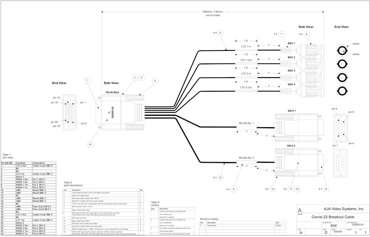
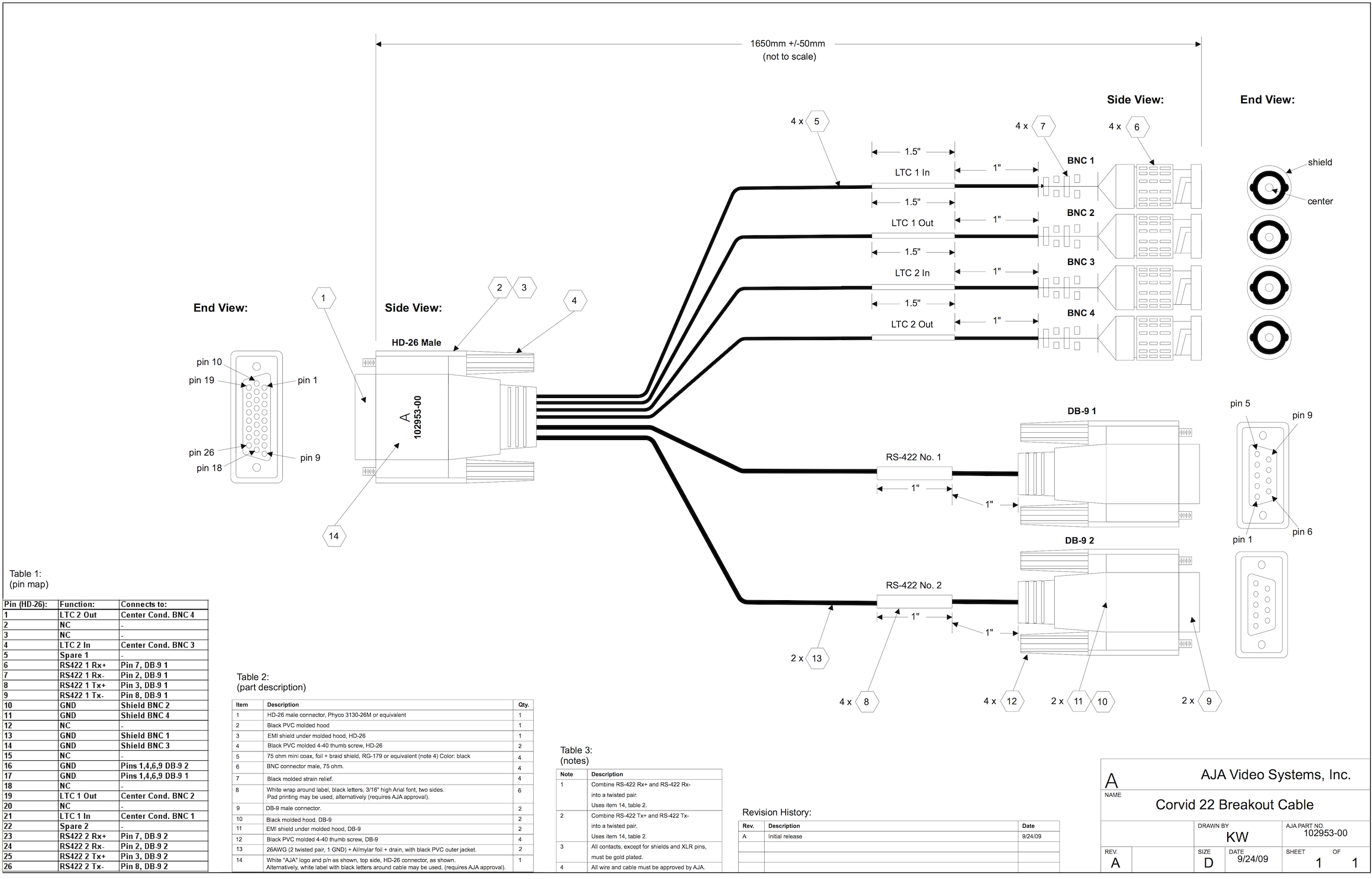
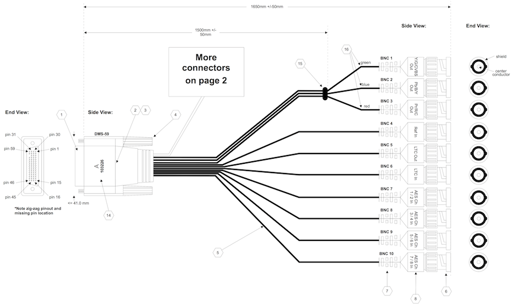
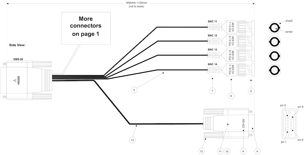
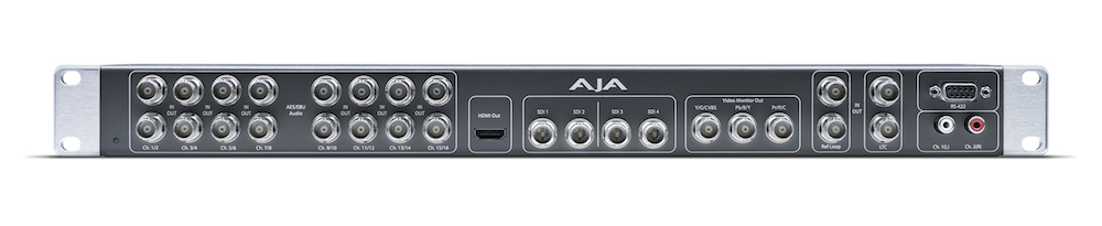
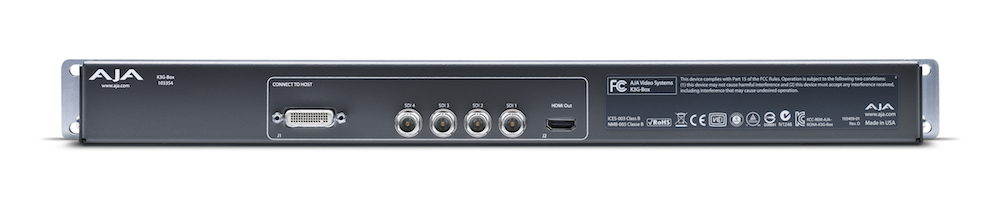

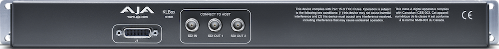
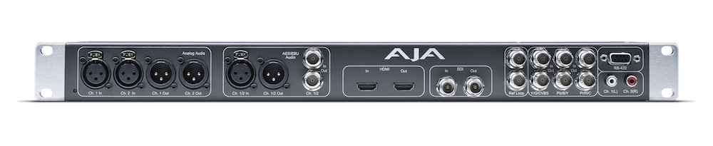
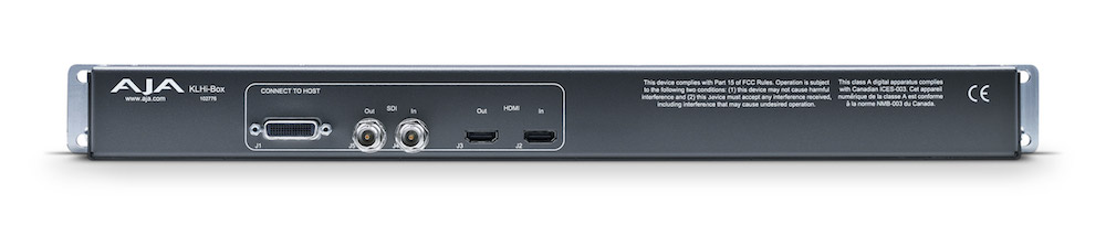
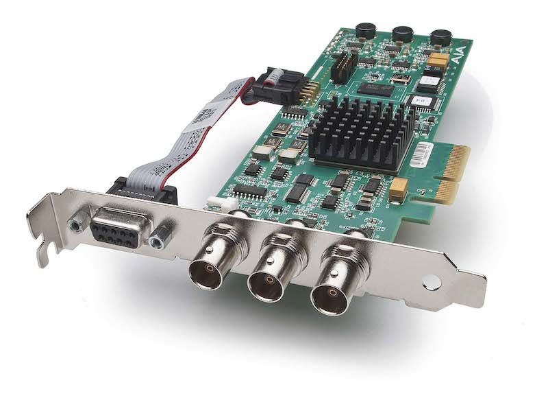
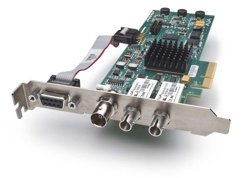
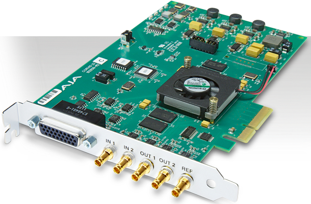
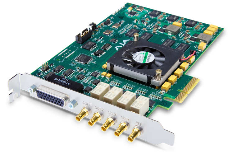
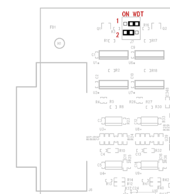
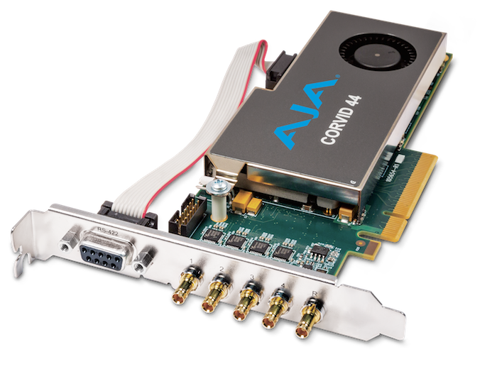
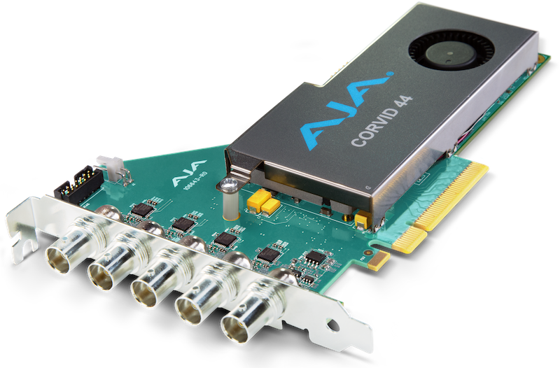
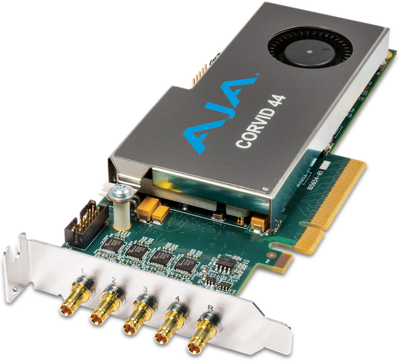
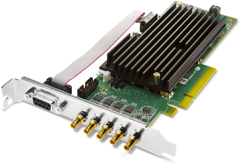
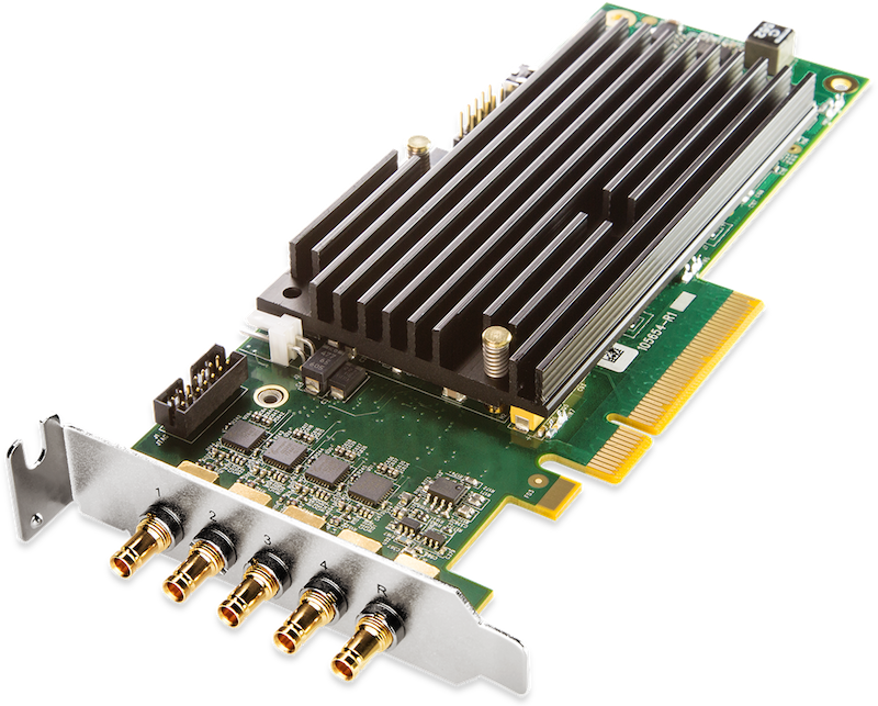
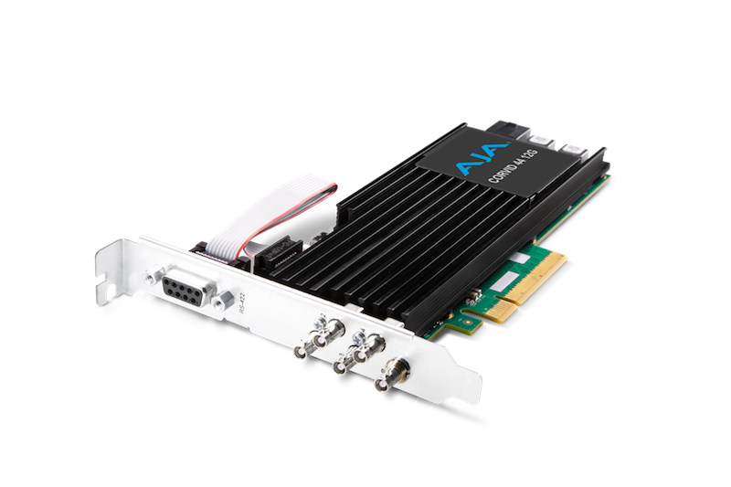
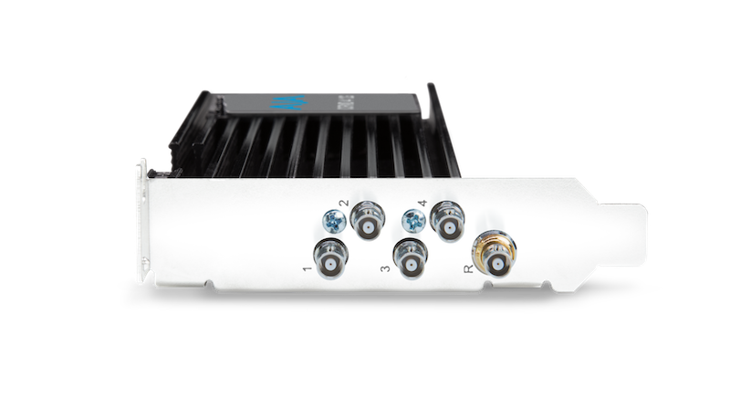
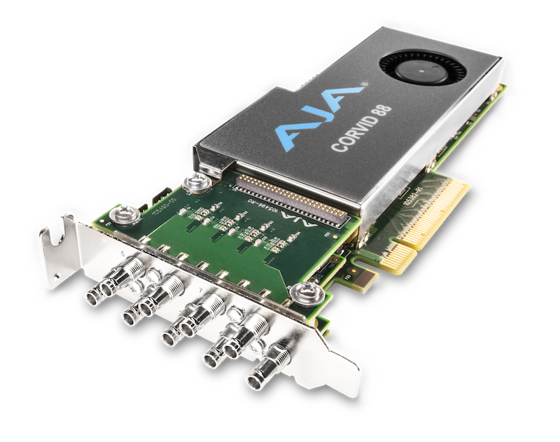
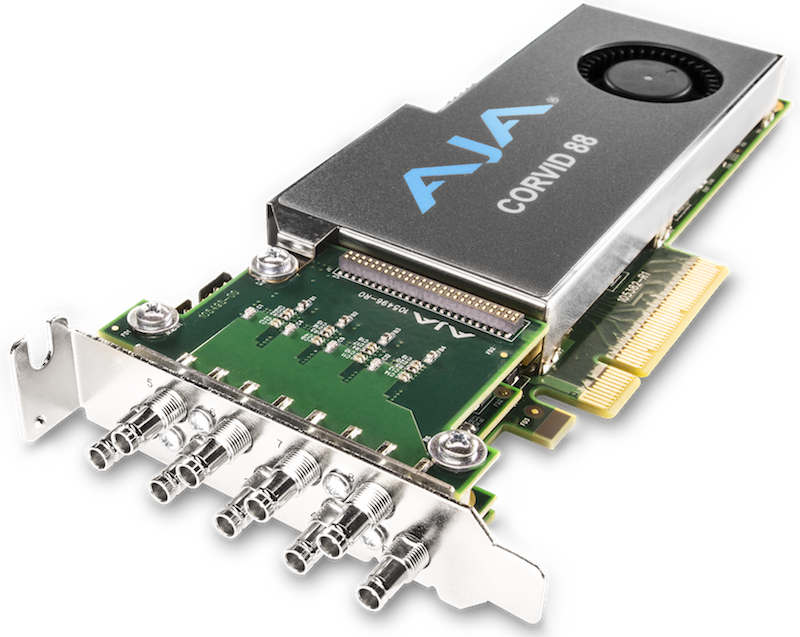
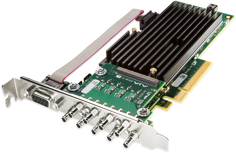
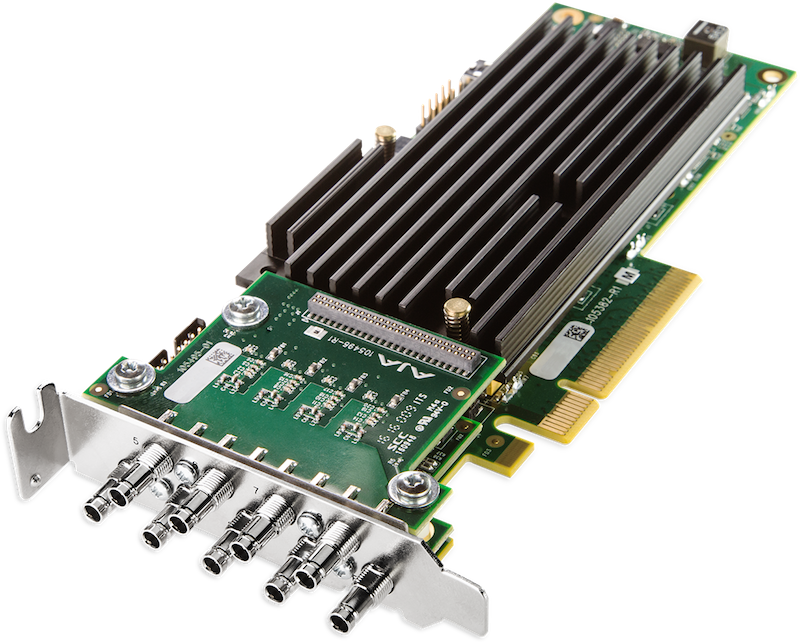
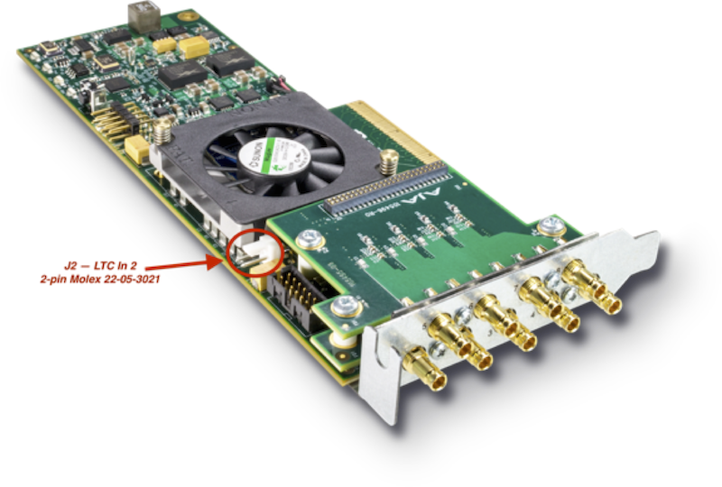
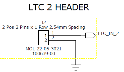
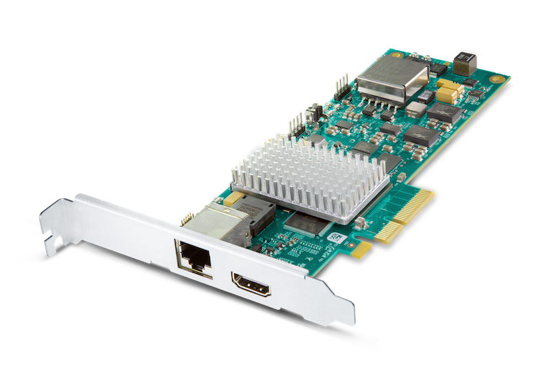
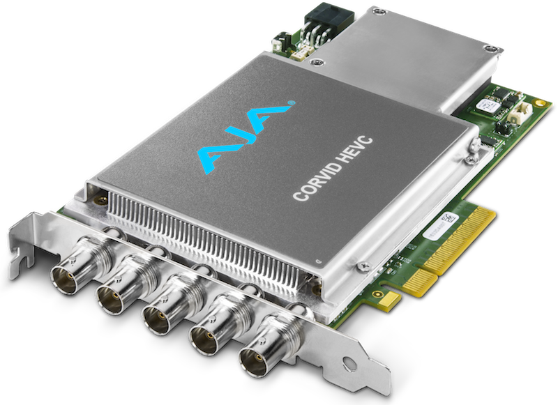
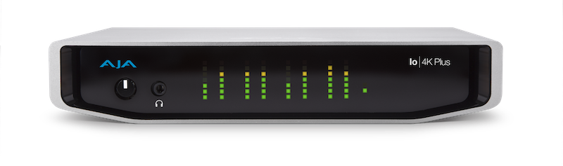
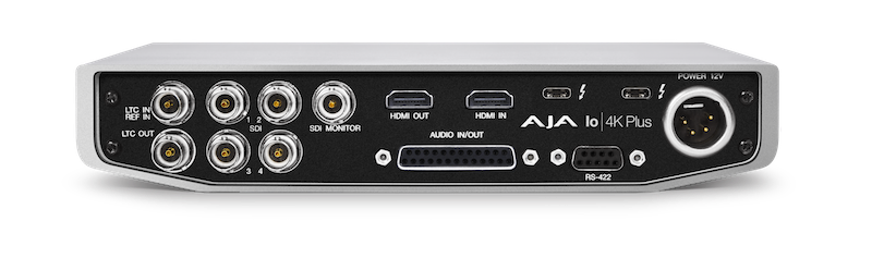
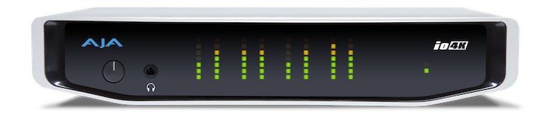
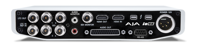
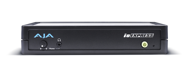
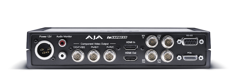
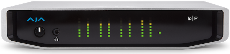
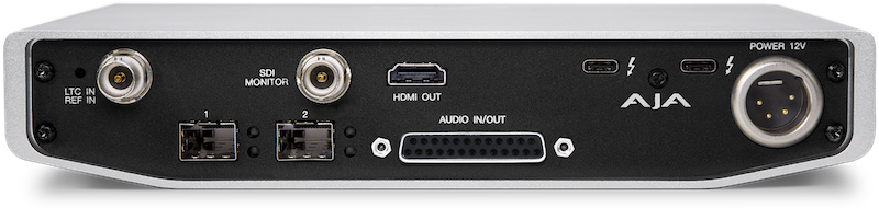
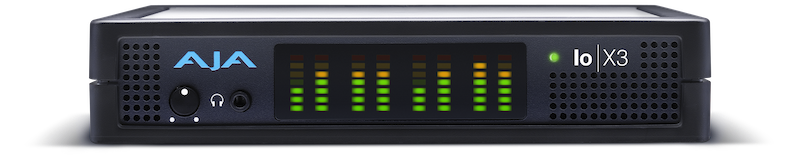
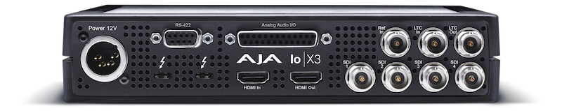
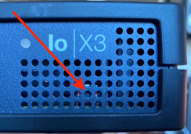
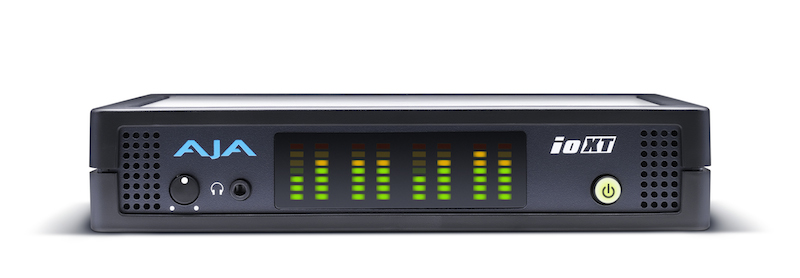
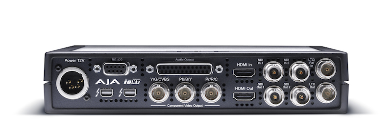
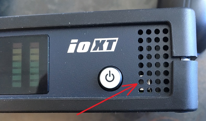
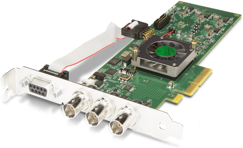
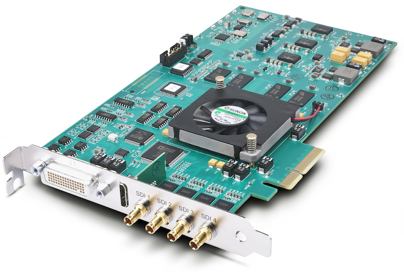
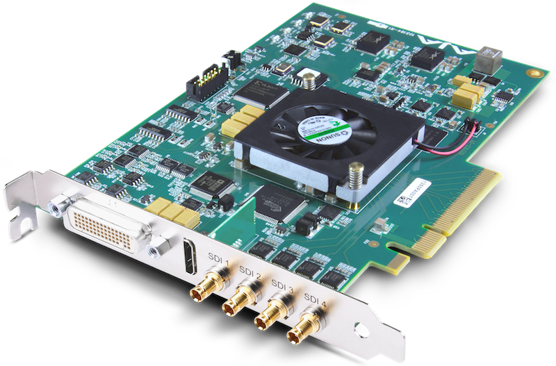
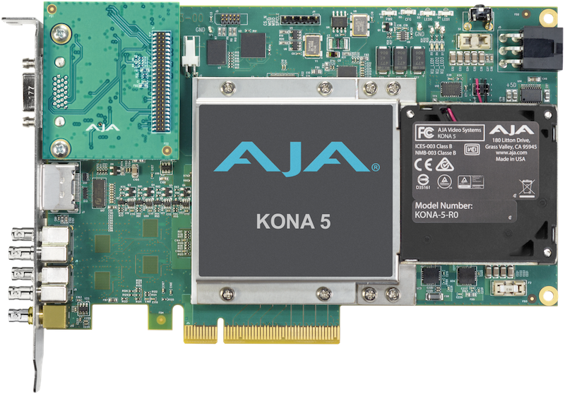
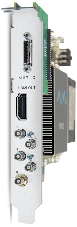
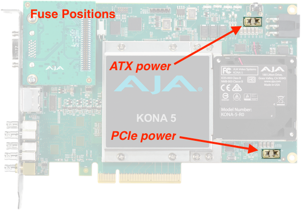
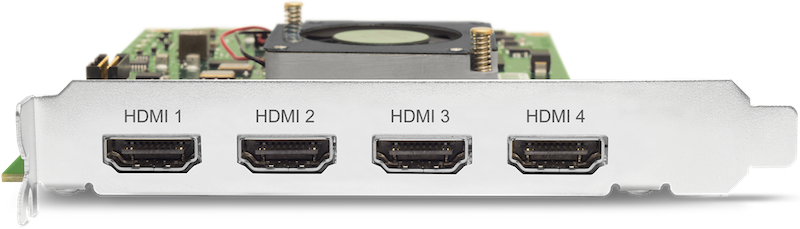
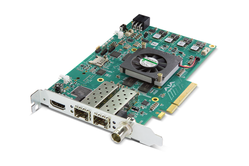
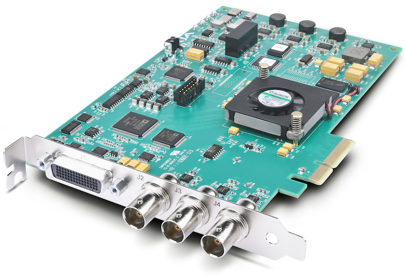
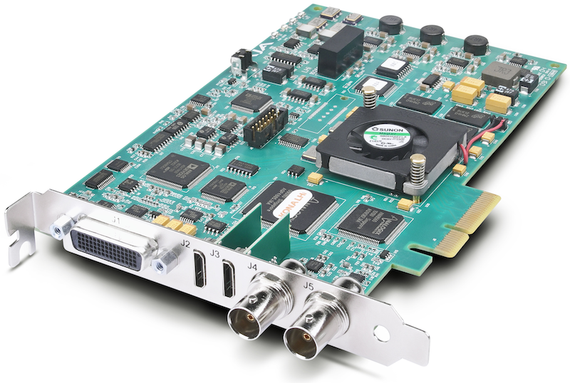
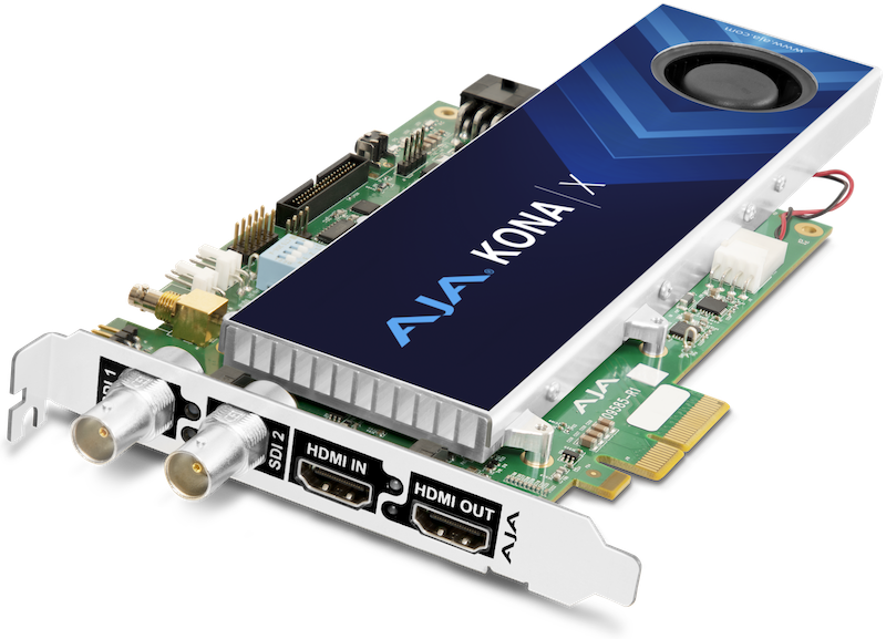
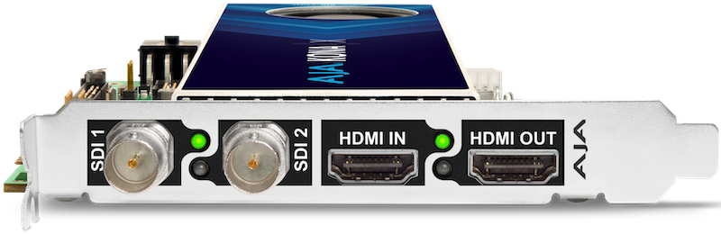
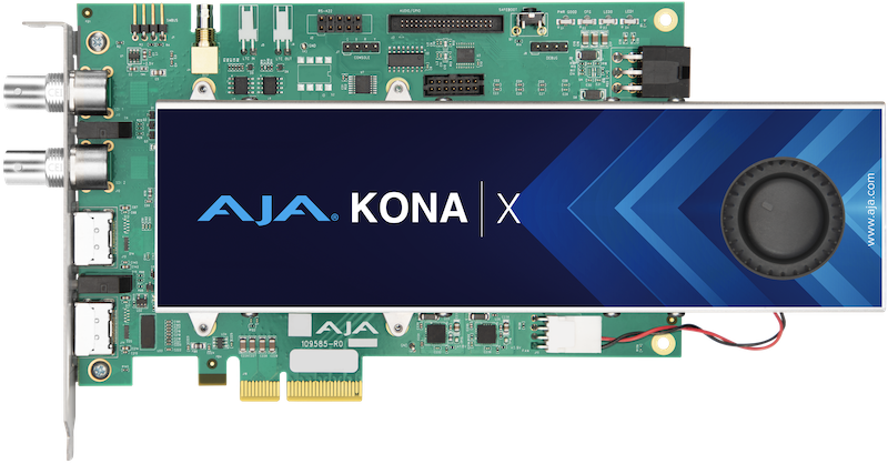
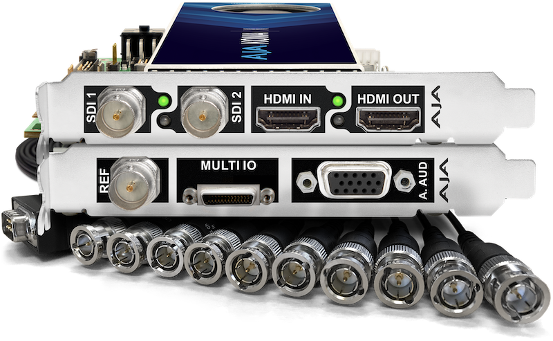
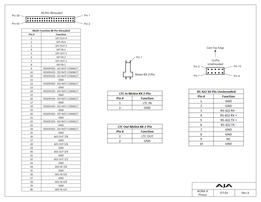
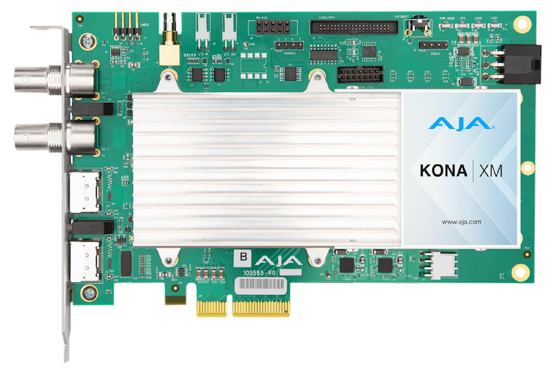
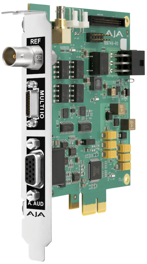
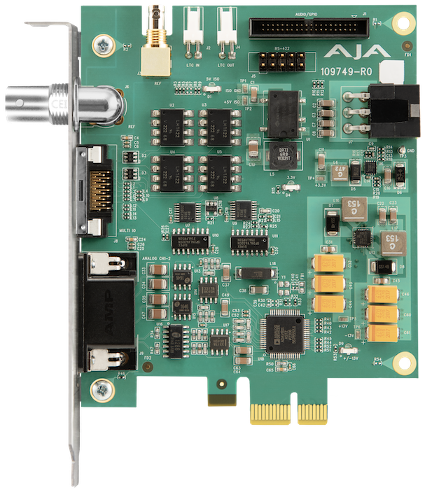
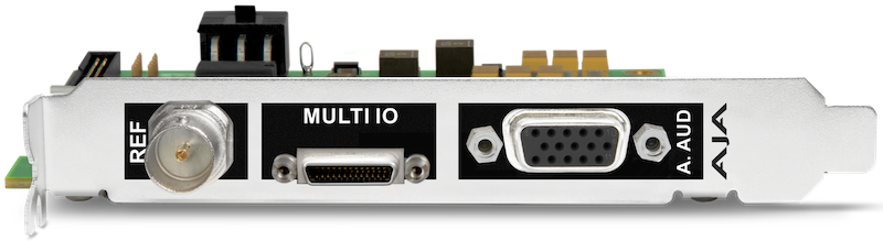
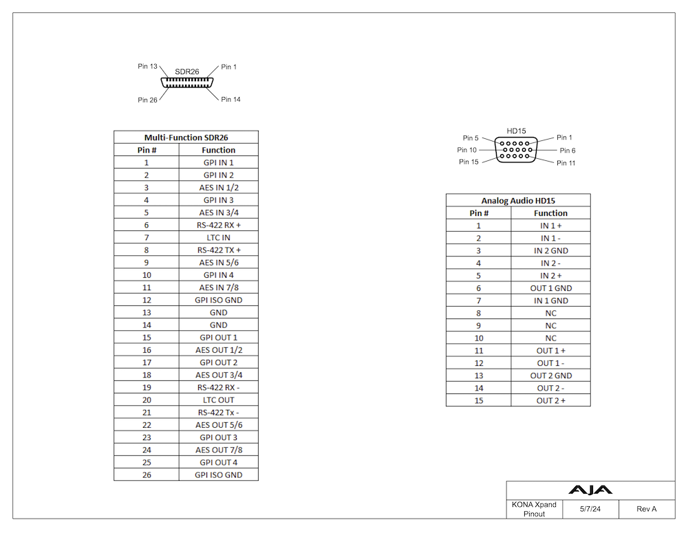
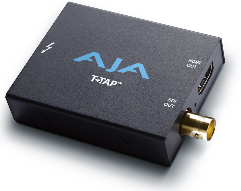
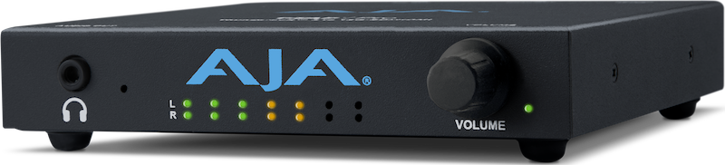
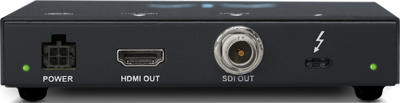
 1.8.17