NTV2 device FPGA firmware implements several types of “widgets“ for receiving, processing and transmitting video data. These can be classified as follows:
Most widgets typically have one or more registers associated with them for reporting status, or to control their operation. Rather than calling CNTV2Card::ReadRegister or CNTV2Card::WriteRegister, client applications should use the appropriate widget-related API calls in the CNTV2Card class to inquire about and/or control the widget of interest.
All widgets have a unique identifier in software expressed by the NTV2WidgetID enumeration. To determine if a device implements a particular widget, call NTV2DeviceCanDoWidget.
Video data paths between widgets are implemented using crosspoints in firmware.
- Widget inputs are identified by NTV2InputCrosspointID.
- Widget outputs are identified by NTV2OutputCrosspointID.
- Input Widgets only have output crosspoint connections.
- Output Widgets only have input crosspoint connections.
- Processing Widgets have both input and output crosspoint connections.
The CNTV2SignalRouter class has static methods that are useful for inquiring about device widgets and their input and output crosspoints:
A set of “crosspoint select” registers (e.g., kRegXptSelectGroup1, kRegXptSelectGroup2, etc.) determine which widget output will feed (source) each widget’s input.
- Note
- A widget’s output can source multiple widgets’ inputs, while a widget’s input can only be sourced by one other widget’s output. In other words, widget outputs are one-to-many, while widget inputs are one-to-one.
-
Widget inputs that are left open — i.e., disconnected — i.e. aren’t connected to any other widget’s output — default to the NTV2_XptBlack output crosspoint.
The CNTV2Card class has several methods dedicated to widget routing:
Due to FPGA size limitations, only a small fraction of the possible widget interconnection routes are implemented. Unfortunately, for many years, there was never a programmatic way to determine at runtime if a device implemented a specific connection path. The CNTV2Card::CanConnect function was in place to support this, but it was never functional. Around SDK 14.0, an attempt was made to compile a static “implemented routes” table for some firmware, but it wasn’t reliable and was abandoned.
Starting with SDK 16.0, newer devices have a firmware ROM bitmask that provides a true indication of actual, implemented connection paths. The CNTV2Card::CanConnect function makes use of this bitmask for those devices that support it.
The NTV2 SDK provides the Routing Inspector in “NTV2Watcher” that graphically shows the available device widgets and the signal routing between them. It lets you inspect and interactively change widget configuration and signal routing paths between widgets. Also, for devices that support this feature, it displays the legal, implemented routes when creating a new connection from a widget socket. Finally, as a programming aid, once a working routing has been achieved, NTV2Watcher can generate the C++ source code that implements it.
Input Widgets
These widgets only have output crosspoints that provide signal sources for signal-processing or output widgets.
- Note
- An input widget’s output can be used to source multiple output and signal-processing widgets’ inputs.
SDI Input
An SDI Input widget represents a physical SDI input connector.
- There is one of these widgets for each input SDI connector (e.g. NTV2_WgtSDIIn1, NTV2_WgtSDIIn2, …).
- For devices that have bi-directional SDI connectors (see NTV2DeviceHasBiDirectionalSDI), there will be one of these widgets for each potential SDI input connector.
- Older devices that only support 1.5Gbps SDI use “non-3G” SDI input widgets — NTV2_WgtSDIIn1, NTV2_WgtSDIIn2, etc.
- Devices that support 3Gbps SDI have “3G” SDI input widgets — NTV2_Wgt3GSDIIn1, NTV2_Wgt3GSDIIn2, etc.
- Devices that support 6Gbps or higher SDI have “12G” SDI input widgets — NTV2_Wgt12GSDIIn1, NTV2_Wgt12GSDIIn2, etc.
- 3Gbps SDI inputs have two output crosspoints — one for DS1, another for DS2, the latter used in dual-link applications. Note that the KONA LHi, AJA’s first 3Gbps SDI board, used NTV2_WgtSDIIn2 for DS1 and NTV2_WgtSDIIn2 for DS2.
- There are two ways to obtain an SDI input’s NTV2OutputCrosspointID …
HDMI Input
An HDMI Input widget represents a physical HDMI input connector.
- There is one of these widgets for each input HDMI connector.
- Older devices with our 1st-generation HDMI chip use NTV2_WgtHDMIIn1.
- Devices that support our 2nd-generation HDMI chip use NTV2_WgtHDMIIn1v2.
- Devices that support our 3rd-generation HDMI chip use NTV2_WgtHDMIIn1v3.
- Devices that support our 4th-generation HDMI chip use NTV2_WgtHDMIIn1v4, etc. Each of these have separate YCbCr and RGB output crosspoints.
- To obtain its NTV2OutputCrosspointID …
- Call GetInputSourceOutputXpt …
- Specify which HDMI input by passing it NTV2_INPUTSOURCE_HDMI1, NTV2_INPUTSOURCE_HDMI2, …etc.
- For 4K/UHD applications, specify the appropriate quadrant number 0, 1, 2 or 3 in the
inHDMI_Quadrant parameter.
- For the RGB output crosspoint instead of the default YUV one (4th-generation HDMI only), pass
true for the inIsHDMI_RGB parameter.
Analog Video Input
An Analog Video Input widget represents a physical analog video input connector (typically RCA connectors labeled Y/G/CVBS, Pb/B/Y and Pr/R/C RCA connectors).
Output Widgets
These widgets only have input crosspoints that accept signals from signal-processing or input widgets.
- Note
- An output widget’s input can only be sourced from a single input or signal-processing widget’s output.
SDI Output
An SDI Output widget represents one of the device’s physical SDI output connectors.
- There is one of these widgets for each output SDI connector (e.g. NTV2_WgtSDIOut1, NTV2_WgtSDIOut2, …).
- For devices that have bi-directional SDI connectors (see NTV2DeviceHasBiDirectionalSDI), there will be one of these widgets for each potential SDI output connector.
- Older devices that only support 1.5Gbps SDI use “non-3G” SDI output widgets — NTV2_WgtSDIOut1, NTV2_WgtSDIOut2, etc.
- Devices that support 3Gbps SDI have “3G” SDI output widgets — NTV2_Wgt3GSDIOut1, NTV2_Wgt3GSDIOut2, etc.
- Devices that support 6Gbps or higher SDI have “12G” SDI output widgets — NTV2_Wgt12GSDIOut1, NTV2_Wgt12GSDIOut2, etc.
- 3Gbps SDI outputs have two input crosspoints: one for data stream 1 (DS1), another for data stream 2 (DS2), DS2 used in dual-link applications (see Dual-Link and 3G Overview ).
- There are two ways to obtain an SDI output’s NTV2InputCrosspointID …
HDMI Output
An HDMI Output widget represents a physical HDMI output connector.
Analog Video Output
An Analog Video Output widget represents a physical analog video output connector (typically RCA connectors labeled Y/G/CVBS, Pb/B/Y and Pr/R/C RCA connectors).
Signal-Processing Widgets
These widgets have both input and output crosspoints. They accept and consume a signal from another source, and perform some kind of processing on it, and send it on to another widget for consumption downstream.
- Note
- A signal-processing widget’s output can source multiple widgets’ inputs, while each of its inputs can only be sourced by one other widget’s output.
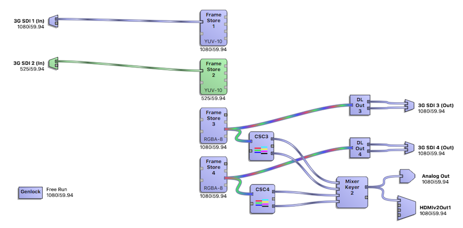
Frame Store
A Frame Store widget represents the firmware entity responsible for writing or reading video frames to or from device SDRAM.
- NTV2DeviceGetNumFrameStores will report the number of Frame Store widgets that are available on a given device.
- Frame Store widgets are identified by NTV2_WgtFrameBuffer1, NTV2_WgtFrameBuffer2, etc.
- In Capture Mode…
- The normal (“Level A”) input crosspoint is available and should be used for most applications.
- There is a “Level B” input crosspoint that is available for dual-link applications.
- Call GetFrameBufferInputXptFromChannel to obtain a Frame Store’s NTV2InputCrosspointID …
- Specify the Frame Store of interest by NTV2Channel (i.e., NTV2_CHANNEL1, NTV2_CHANNEL2, …etc.).
- By default, the function returns the normal “Level A” input crosspoint. Specify
true for inIsBInput for the “Level B” crosspoint.
- In Playout Mode…
- If the Frame Store is configured for SD, HD, or 4K/UHD Quads/Squares (i.e. non-Tsi) mode:
- If the Frame Store is configured for 4K/UHD Tsi (SMPTE 425 two-sample-interleave) mode:
- Call GetFrameBufferOutputXptFromChannel to obtain a Frame Store’s NTV2OutputCrosspointID …
- Specify the Frame Store of interest by NTV2Channel (i.e., NTV2_CHANNEL1, NTV2_CHANNEL2, …etc.).
- By default, the function returns the YUV output crosspoint. If the Frame Store’s NTV2FrameBufferFormat is an RGB format, pass
true for inIsRGB to obtain the RGB crosspoint.
- By default, the function will return a normal, non-SMPTE-425 (non-Tsi) output crosspoint. If the Frame Store is configured for 4K/UHD and for two-sample-interleave, pass
true for inIs425, to obtain the “425” crosspoint.
See the FrameStore Operation section for information about how to programmatically interrogate and configure Frame Stores.
ColorSpace Converter (CSC) Routing
A ColorSpace Converter widget represents the firmware entity that can convert YCbCr video into RGBA or vice-versa.
- NTV2DeviceGetNumCSCs reports the number of CSC widgets that are available on a given device.
- CSC widgets are identified by NTV2_WgtCSC1, NTV2_WgtCSC2, etc.
- Each CSC has two input crosspoints:
- Video Input: When this is sourced from another widget’s output crosspoint, and it’s receiving…
- YCbCr/YUV video, then the CSC will produce valid RGB[A] data on its RGBA output crosspoint.
- RGB[A] video, then the CSC will produce valid YCbCr data on its YUV output crosspoint.
- Key Input: This supplies the alpha channel data for the CSC’s RGBA output.
- Call GetCSCInputXptFromChannel to obtain the NTV2InputCrosspointID for a CSC:
- Specify the CSC by NTV2Channel (e.g., use NTV2_CHANNEL3 for CSC 3).
- By default, the function returns the video input crosspoint. To obtain the alpha/key input crosspoint, pass
true for inIsKeyInput.
- Each CSC has 3 output crosspoints:
- YUV Video: This will produce valid YCbCr video data only when the CSC’s Video Input is receiving RGB[A] video data.
- RGB Video: This will produce valid RGB[A] video data only when the CSC’s Video Input is receiving YCbCr video data.
- Key YUV: This will produce valid YCbCr key data only when the CSC’s Video Input is receiving RGB[A] video data.
- Call GetCSCOutputXptFromChannel to obtain one of the CSC’s NTV2OutputCrosspointID values:
- Specify the CSC by NTV2Channel (e.g., use NTV2_CHANNEL3 for CSC 3).
- By default, the function returns the video output crosspoint. To obtain the Key crosspoint, pass
true for inIsKey.
- By default, the function returns the YUV output crosspoint. To obtain the RGB crosspoint, pass
true for inIsRGB.
The Color Space Converter Operation section has more information on CSC configuration.
LUT Routing
A LUT widget represents the firmware entity that converts R, G, and B values into different R, G, and B values.
- NTV2DeviceGetNumLUTs reports the number of LUT widgets that are available on a given device.
- LUT widgets are identified by NTV2_WgtLUT1, NTV2_WgtLUT2, etc.
- Each LUT has one input crosspoint:
- Each LUT has a single output crosspoint:
- Video Output: This emits the converted RGB video data.
- Call GetLUTOutputXptFromChannel to obtain the LUT’s NTV2OutputCrosspointID value:
- On very old devices, the one and only LUT also had a Key Output that emitted luminance data in the Y channel of a YCbCr signal from the crosspoint. For this output, use NTV2_XptLUT1YUV.
The LUT Operation section has more information on LUT configuration.
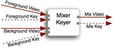
Mixer/Keyer Routing
A Mixer/Keyer widget represents the firmware entity that can mix two YCbCr video sources into a single YCbCr raster (and key).
- Each Mixer/Keyer widget has four input crosspoints:
- Foreground Inputs:
- Video: This determines the video that will appear in the foreground of the mix, and should be routed to a widget that produces YCbCr video.
- Key: This determines the foreground key, and should be routed to another widget’s YCbCr output. Only the Y component is used — the Cb and Cr components are ignored.
- Call GetMixerFGInputXpt to obtain a foreground NTV2InputCrosspointID:
- Specify the NTV2Channel used. (The actual zero-based Mixer index that’s used will be half the ordinal value of NTV2Channel.)
- Pass
false for inIsKey for the Video input; pass true for the Key input.
- Background Inputs:
- Video: This determines the video that will appear in the background, and should be routed to a widget that produces YCbCr video.
- Key: This determines the background key, and should be routed to another widget’s YCbCr output. Note that only the Y component is used — the Cb and Cr components are ignored.
- Call GetMixerBGInputXpt to obtain a background NTV2InputCrosspointID:
- Specify the NTV2Channel used. (The actual zero-based Mixer index that’s used will be half the ordinal value of NTV2Channel.)
- Pass
false for inIsKey for the Video input; pass true for the Key input.
- Each Mixer/Keyer widget has two output crosspoints:
- Video Output: This produces the mixed/keyed YCbCr video raster.
- Key Output: This produces a YCbCr signal with the resulting mixed key data in the Y channel.
- Call GetMixerOutputXptFromChannel to obtain a Mixer’s NTV2OutputCrosspointID:
- Specify the NTV2Channel used. (The actual zero-based Mixer index that’s used will be half the ordinal value of NTV2Channel.)
- Pass
false for inIsKey for the Mixer’s Video output; pass true for the Mixer’s Key output.
End-to-End (E-E) Routing
This section shows how to programmatically set up a device to pass through an input signal to at least one corresponding output.
TBD
Routing for Capture
This section shows how to programmatically set up a device to receive video for several commmon scenarios.
- SD/HD YCbCr
TBD
- SD/HD RGB
TBD
- SD/HD RGB Over-the-Wire Dual-Link
TBD
Routing for Playout
This section shows how to programmatically set up a device for transmitting video for several commmon scenarios.
- SD/HD YCbCr Playout From YCbCr Frame Buffer
- SD/HD YCbCr Playout From RGB Frame Buffer
- HD RGB Playout Over 2 × 1.5G Dual-Link SDI From YCbCr Frame Buffer
TBD
- HD RGB Playout Over 1 × 3G Dual-Link SDI From YCbCr Frame Buffer
TBD
- HD RGB Playout Over 2 × 1.5G Dual-Link SDI From RGB Frame Buffer
TBD
- HD RGB Playout Over 1 × 3G Dual-Link SDI From RGB Frame Buffer
- HD HFR YCbCr Playout Over 2 × 3G SDI From YCbCr Frame Buffer
TBD
- HD HFR YCbCr Playout Over 2 × 3G SDI From RGB Frame Buffer
TBD
- 2K×1080 YCbCr Playout Over 2 × 3G SDI From YCbCr Frame Buffer
TBD
- HD HFR YCbCr Playout Over 2 × 3G SDI From RGB Frame Buffer
TBD
- UHD/4K 4:2:2 YCbCr Playout Over 4 × 3G SDI (“Squares”)
TBD
- UHD/4K 4:2:2 YCbCr Playout Over 4 × 3G SDI (“Two-Sample Interleave”)
TBD
- UHD/4K 4:2:2 YCbCr Playout Over 2 × 6G SDI (“Two-Sample Interleave”)
TBD
- UHD/4K 4:2:2 YCbCr Playout Over 1 × 12G SDI
TBD
End-to-End (E-E) Routing
This section shows how to programmatically set up a device for transmitting input video with a variety of latencies.
- SD/HD YCbCr E-E (Sub-Frame Latency)
TBD
- SD/HD YCbCr Frame Synchronizer (One-Frame Latency)
TBD
- HD E-E Mix RGBA Graphic Over Live Video
with sub-frame latency TBD
- HD HFR YCbCr E-E Over 2 × 1.5G Dual-Link SDI
TBD
- HD HFR YCbCr E-E Over 1 × 3G Dual-Link SDI
TBD
- E-E Over 2 × 3G SDI
TBD
- E-E Over 1 × 6G SDI
TBD
4K and 8K Background
There is quite a history with 4K/Quad. Since the introduction of 1.5G HD signaling, the SDI image size has quadrupled twice.
The first time from HD to UHD we called it “Quad“, since it required 4 × HD connections. Initially, each link was a square division of the quad image –– so “quad squares”.
Then SMPTE devised TSI (a.k.a. 2SI or two-sample-interleaved), with each link carrying a subsample of the whole image, which we then called “Quad TSI”. To make TSI from a planar image requires a simple kind of muxing, so mux widgets were added to the firmware, which had to be routed before the FrameStore (for capture). For playback, demux widgets were added and must be routed after the FrameStore. We call this “TSI routing”.
The firmware could now do SD up to 4K of all the various SD, HD, and 3G SDI formats. The kona4, Corvid 44 and Corvid 88 are good examples of devices that supported these 3G crosspoints and the full complement of TSI muxers/demuxers.
When 12G came along, we designed the KONA 5 and this same quadrupling started all over again. The 8K/UHD2 firmware now has a 12G crosspoint, so we can route UHD signals like HD ones on the kona4. Initially UHD2 was square division too, and of course, SMPTE added TSI. These formats became “Quad-Quad Squares” and “Quad-Quad TSI” … only this time we built the muxers/demuxers into the FrameStores, which greatly simplifies the routing, and can be inferred from the format.
There is still a difference in the way FrameStores are routed to make “squares” and TSI work on the KONA 5 and Corvid 44 12G. Square division requires 4 FrameStores, since the “squares” are simultaneously read from different places in the image. TSI only requires 2 FrameStores, since it only reads from 2 lines at a time.

 1.8.17